Printed Circuit Board Connector Wiring Diagram Si18-525B
76 Printed Circuit Board Connector Wiring Diagram
1.4 Duct Connected Type
Connectors PCB(1) (Control PCB)
PCB(2) (Display PCB)
Note: Other designations
PCB(1) (Control PCB)
PCB(2) (Display PCB)
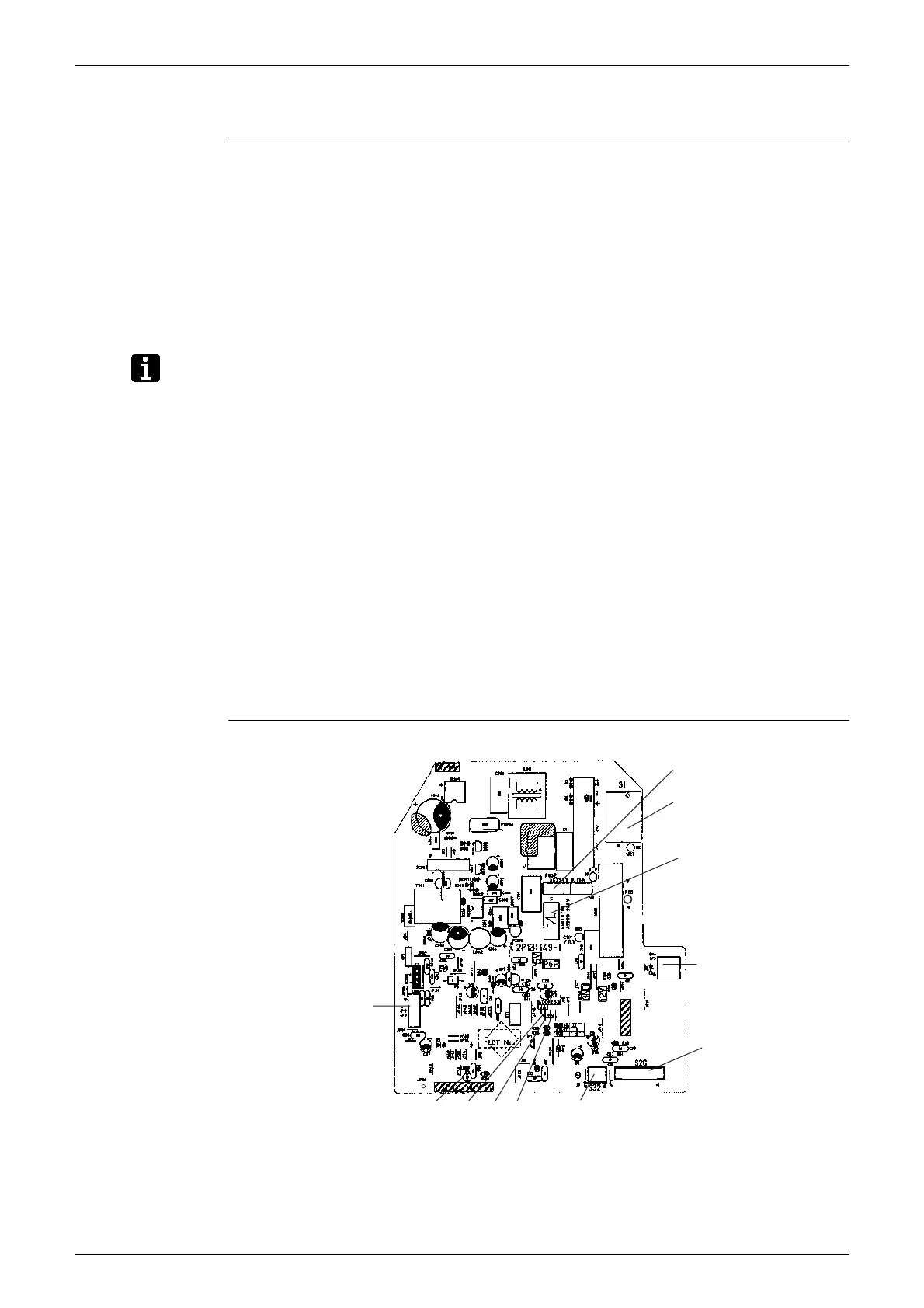
PCB Detail PCB (1): Control PCB
1) S1 Connector for AC fan motor
2) S7 Connector for AC fan motor
3) S21 Connector for centralized control to 5 rooms
4) S26 Connector for display PCB
5) S32 Connector for heat exchanger thermistor
1) S1 Connector for control PCB
1) V1 Varistor
2) JA Address setting jumper
JB Fan speed setting when compressor is OFF on thermostat
JC Power failure recovery function
∗
Refer to page 193 for more detail.
3) LED A LED for service monitor (green)
4) FU1 Fuse (3.15A)
1) SW1 (S1W) Forced operation ON/OFF switch
2) LED1 LED for operation (green)
3) LED2 LED for timer (yellow)
4) LED3 LED for HOME LEAVE operation (red)
5) RTH1 (R1T) Room temperature thermistor
S1
V1
S7
S26
S32JCJBJA
S21
2P131149
LED A
FU1
 Loading...