EasyManua.ls Logo

Daikin IM 986-2 VHC User Manual

Daikin IM 986-2 VHC
48 pages
To Next Page IconTo Next Page
To Previous Page IconTo Previous Page
Page #12 background imageLoading...
Page #12 background image
Page 12 of 48 / IM 986-2
Cabinet Configurations
Figure 12: Single Side Discharge
Figure 13: Double Side Discharge
Figure 14: Side & Top Discharge (See Notice on page 11) Figure 15: Double Side & Top Discharge (See Notice on page 11)
Figure 16: Top Discharge (See Notice on page 11) Figure 17: Closed Plenum – Field Modication Required
= Return Riser = Supply Riser = Drain = Return Air = Discharge Air = Top Discharge

Table of Contents

Question and Answer IconNeed help?

Do you have a question about the Daikin IM 986-2 VHC and is the answer not in the manual?

Daikin IM 986-2 VHC Specifications

General IconGeneral
Model NumberIM 986-2 VHC
CategoryHeat Pump
Heating Capacity9.8 kW
Cooling Capacity8.6 kW
RefrigerantR410A

Summary

Model Nomenclature

Receiving and Storage

Cabinet Skid Handling

Procedures for handling and stacking cabinet skids during transport and storage.

Chassis Skid Handling

Procedures for handling and stacking chassis skids during transport and storage.

Storage and Operating Environment

Recommended environmental conditions for unit storage and operation.

Handling and General Information

Unit Handling Procedures

Guidelines for safely handling the unit and its components during installation.

General Installation Information

Overview of design, application, and installation standards for the units.

Disassembling Cabinet Sections

Separating Upper and Lower Cabinet Sections

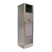
Step-by-step guide to disassemble the unit cabinet into upper and lower sections.

Dimensional Data

Pre-Installation Considerations

Optimizing Unit Performance and Noise

Tips for minimizing noise and vibration for optimal unit performance.

Cabinet Configurations

Typical Framing and Discharge Arrangements

Critical Dimensions

Return Air Grille/Panel Dimensions

Specific dimensions for the return air grille/panel installation and fit-up.

Installation Procedure

Risers and Cabinet Installation

Steps for positioning and securing the unit cabinet and connecting risers.

Cleaning and Flushing Water System

Procedure for cleaning and flushing the water system before unit operation.

Power Wiring Installation

Instructions for connecting the unit's power supply wiring from the building.

Condensate Drain Hose Connection

Steps for connecting the condensate drain hose to the unit's drain stub out.

Water Connections and Valves

Guidelines for making water piping connections and installing valves.

Flexible Hose Connections

How to make flexible hose connections to supply and return valves from riser stub-outs.

Installing Unit Chassis

Steps for installing the unit chassis into the cabinet.

Cabinet to Chassis Wiring

Procedure for connecting wiring between the cabinet and chassis components.

Remote Control Node (RCN) Installation

Instructions for installing the optional Remote Control Node (RCN).

Return Air Grille/Panel Installation

Steps for installing the return air grille/panel assembly.

Discharge Air Diffuser Installation

Instructions for installing the discharge air diffuser.

Twin Units Installation

MicroTech III Unit Controller

Controller Features and Fault Outputs

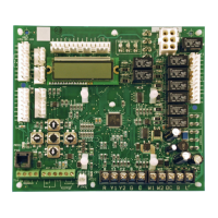
Overview of controller features, LED indicators, and fault output sequences.

Remote Reset Feature

Explanation of the remote reset feature for automatic lockouts.

MicroTech III Unit Controller Terminals

Terminal Locations and Descriptions

Detailed descriptions of terminal locations and their functions on the unit controller.

MicroTech III Unit Controller Terminal Layout

I/O Expansion Module

MicroTech III Controller with LONWORKS Module

MicroTech III Controller with BACnet Module

Typical Wiring Diagram (PSC Motor)

Typical Wiring Diagram (PSC Motor 265-277V)

Typical Wiring Diagram (X13 Motor 208-230V)

Typical Wiring Diagram (X13 Motor 265-277V)

Start-up and Operation

Manual Operation Modes

How to manually operate the unit in cooling or heating modes.

Thermostats and Wall Sensors

Overview of available thermostats and wall sensors for unit control.

Thermostat Specifications

Wireless Temperature Control System

Remote Control Node (RCN)

Description of the Remote Control Node (RCN) for wireless control.

MicroTech III Wall-Mounted Room Sensors

Optional Control Accessories

Motorized Isolation Valve & Relay

Details on the motorized isolation valve kit and its wiring.

Troubleshooting

R-410A Refrigerant Information

Properties, lubrication, charging, and safety of R-410A refrigerant.

General Maintenance

Routine maintenance tasks including filter changes and system checks.

Troubleshooting Refrigeration Circuit

Troubleshooting Unit Operation

General Use and Information

Related product manuals