IM 986-2 / Page 37 of 48
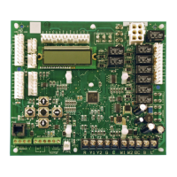
Typical Wiring Diagram
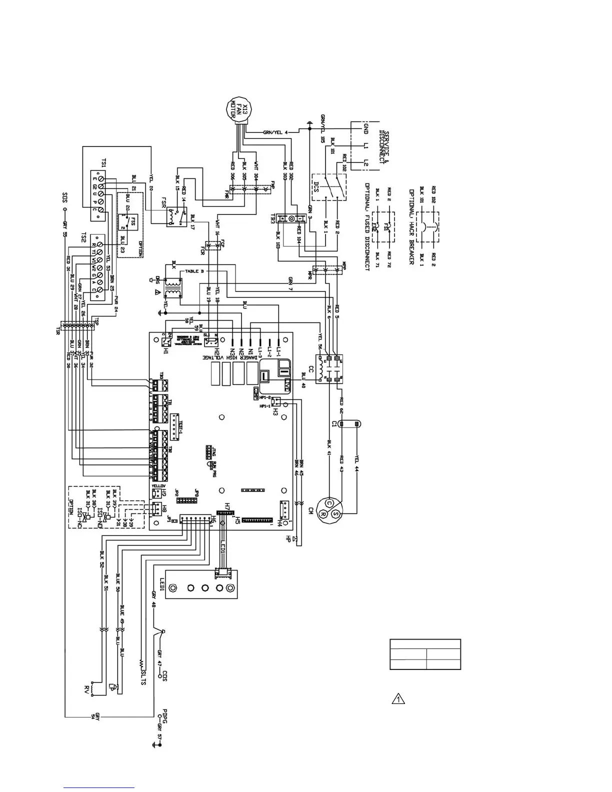
Figure 51: MicroTech III Unit Controller, 2-Speed Fan (Toggle or Thermostat), X13 Motor 208-230/60Hz/1-Phase,
Unit Sizes 021-036
Table B
208V
RED
230V ORG
Drawing No. 669349701
Legend
Item
Description
C1
Capacitor-Compressor
C2
Capacitor-Fan
CC
Compressor Contactor
CM
Compressor - Motor
COS Condensate Overow Sensor
DSC
Disconnect Switch
FMP
Fan Motor Connector Plug
FMR Fan Motor Connect Receptacle
FCP
Fan Connector Plug
FCR
Fan Connector Receptacle
FPR Fan Power Relay
FSR Fan Speed Relay
FSS
Fan Speed Switch - Optional
FS1 Fuse 1
FS2 Fuse 2
HP
High Pressure Switch
ISO
Isolation Valve - Optional
LED1
LED Annunciator / Harness
LP
Low Pressure Switch
MIII MicroTech III Main Board
MPP
Main Power Connector Plug
MPR
Main Power Connector Receptacle
PDPG Primary Drain Pan Ground
RV
Reversing Valve Solenoid
SOS
Secondary Overow Sensor
SLTS
Suction Line Temp Sensor
TB3 Terminal Block
TS1 Fan Speed Terminal Strip
TS2 Thermostat Terminal Strip
TSP
Terminal Strip Connector Plug
TSR Terminal Strip Connector Terminal
X1
Transformer
Note:
T
ransformer:
Unused wire to be capped.
 Loading...