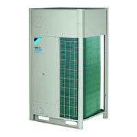
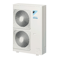
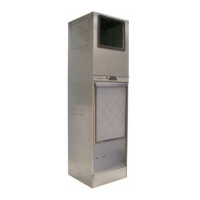
Page 28 of 48 / IM 986-2
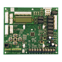
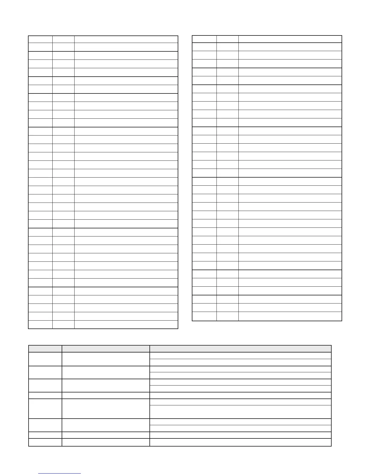
MicroTech® III Unit Controller Terminal Locations and Descriptions
H1 - 1 24 24 VAC Power Input
H1 - 2 C 24 VAC Common
H2 - 1 SL1 Fan Output - Switched L1
H2 - 2 Blank Terminal
H2 - 3 N Fan Neutral
H3 - 1 HP1-1 High Pressure Switch 1 Input Terminal 1
H3 -2 HP1-2 High Pressure Switch 1 Input Terminal 2
H4 - 1 Discharge Air Temp Common
H4 - 2 Discharge Air Temp Signal
H4 - 3 Leaving Water Temp Common
H4 - 4 Leaving Water Temp Signal
H5 - 1 1 I/O Exp Module Common (Gnd)
H5 - 2 I/O Exp Module Common (Gnd)
H5 - 3 I/O Exp Module +5 VDC
H5 - 4 I/O Exp Module SPI CE1
H5 - 5 I/O Exp Module SPI CLK
H5 - 6 I/O Exp Module SPI OUT
H5 - 7 I/O Exp Module SPI IN
H5 - 8 I/O Exp Module +12 VDC
H5 - 9 I/O Exp Module 24 VAC
H5 - 10 I/O Exp Module 24 VAC
H5 - 11 Spare
H5 - 12 Spare
H6 - 1 1 Condensate Overow Signal Input
H6 - 2 Low Temp 1 Sensor Common
H6 - 3 Low Temp 1 Sensor Signal
H6 - 4 Low Pressure Switch 1 Source Voltage
H6 - 5 Low Pressure Switch 1 Signal
H6 - 6 Reversing Valve 1 Common
H6 - 7 Reversing Valve 1 Output
H7 - 1 1 Dummy Terminal
H7 - 2 Dummy Terminal
H7 - 3 Red LED Output
H7 - 4 Green LED Output
H7 - 5 Yellow LED Output
H7 - 6 Red-Green-Yellow LED Common
H8 - 1 1 Isolation Valve/Pump Request Relay N/O
H8 - 2 Isolation Valve/Pump Request Relay N/C
H8 - 3 24 VAC Common
H9 - 1 1 Return Air Temperature Signal
H9 - 2 Return Air Temperature Common
TB1 - 1 1 Room Sensor LED Output
TB1 - 2 2 Fan Mode / Heat-Cool-Auto Input
TB1 - 3 3 Setpoint Adjust Input
TB1 - 4 4 Room Temperature Sensor / Tenant Override
TB1 - 5 5 DC Signal Common
Test-1 R 24 VAC
Test-2 W2 Heat Stage 2 Input
Test-3 W1 Heat Stage 1 Input
Test-4 Y2 Cool Stage 2 Input
Test-5 Y1 Cool Stage 1 Input
Test-6 G Fan
TB2 - 1 R 24 VAC
TB2 - 2 A Alarm Output
TB2 - 3 W2 Heat Stage 2 Input
TB2 - 4 W1 Heat Stage 1 Input
TB2 - 5 Y2 Cool Stage 2 Input
TB2 - 6 Y1 Cool Stage 1 Input
TB2 - 7 G Fan Input
TB2 - 8 O Tenant Override Input
TB2 - 9 C 24 VAC Common
TB3 - 1 E Mark IV Emergency Shutdown Input
TB3 - 2 U Mark IV Unoccupied/Occupied Input
L1 - 1 L1 - 1 Line Voltage Terminal 1
L1 - 2 L1 - 2 Line Voltage Terminal 2
L1 - 3 L1 - 3 Line Voltage Terminal 3
N1 N1 Neutral Terminal 1
N2 N2 Neutral Terminal 2
N3 N3 Neutral Terminal 3
Jumper Description Options
JP1 Mode
Open for normal operation mode
Shorted for service/test operation mode
JP2 Fan operation only applies to Open for continuous fan operation
network controls Shorted for cycling fan operation
JP3 Freeze protection
Open for water freeze protection
Shorted for antifreeze protection
JP4 Future spare Future spare
JP5 Set point adjustment range only Open for adjustment range of -3.0° to +3.0° F
applies to network controls with a Shorted for 50° to 90° F adjustment range
room temperature sensor
JP6 Room control type
Open for thermostatic room control
Shorted for room temperature sensor control, MicroTech III only
JP7 Future spare Future spare
JP8 Future spare Future spare
Table 7: Conguration Jumper Settings
 Loading...