IM 986-2 / Page 39 of 48
Start-up
Cooling or Heating – Manual Operation
Adjust the thermostat heating or cooling setpoint to
maintain desired space temperature.
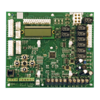
The MicroTech III unit controller has built-in features
such as random start, compressor time delay, night
setback, load shed, shutdown, condensate overow
protection, defrost cycle, brownout, and LED/fault
outputs. Table 10 shows the LED and fault output
sequences. The 24 volt low voltage terminal strip is set
so R-G energizes the fan. R-W1 energizes the fan and
compressor and reversing valve for heating operation.
R-Y1 energizes the fan and compressor for cooling
mode of operation.
The reversing valve is set up to be energized in the
heating mode. The circuit board has a fan interlock
circuit to energize the fan whenever the compressor is
on.
The MicroTech III unit controller has a lockout circuit
to stop compressor operation if any one of its safeties
opens (high pressure or suction line sensor). If the
suction line low temperature sensor opens, the unit will
go into the cooling mode for 60 seconds to defrost any
slush in the water-to-refrigerant heat exchanger.
After 60 seconds, the compressor is locked out. If
the condensate sensor detects a lled drain pan, the
compressor operation will be suspended only in the
cooling mode. The unit is reset by opening and closing
the disconnect switch on the main power supply to the
unit in the event the unit compressor operation has been
suspended due to low suction line sensor reaching its
set point, or a high pressure switch.
The MicroTech III unit controller has a fault output
signal to an LED on a wall thermostat. Table 10 shows
in which function the fault output is “on” (sending a
signal to the LED).
Units must be checked for water leaks upon initial water
system start-up. Water leaks may be a result of mishan-
dling or damage during shipping. Failure by the installing
contractor to check for leaks upon start-up of the water
system could result in property damage.
CAUTION
IMPORTANT
Table 10: LED Fault Indicators
Each water source heat pump unit has a compressor and
blower motor. Each component part has and internal
temperature and amperage sensitive overload. If the over-
load opens it will suspend unit operation. Check component
parts by measuring the winding resistance and looking for
an open circuit.
Additional Accessories – General
Thermostats and Wall Sensors
Easy-to-operate comfort command centers provide a
complete range of deluxe features.
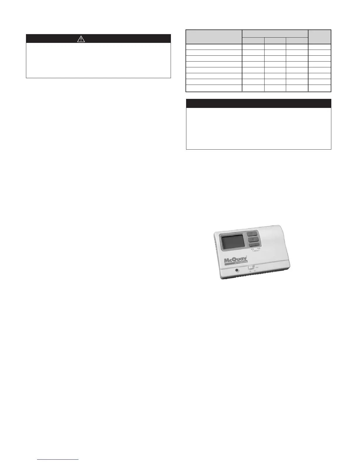
Wall-Mounted Programmable Electronic
Thermostat (P/N 668810301)
1 Heat/1 Cool, Auto Changeover, Hardwired
• 7-Day, 5-2-Day 5-1-1 Day Programmable
• Congurable
• Single-Stage Heat/Cool Systems
• Single-Stage Heat Pump Systems
• Large Display With Backlight
• Selectable Fahrenheit or Celsius
• Compatible with Gas, Oil, or Electric
• SimpleSet™ Field Programming
• Status Indicator Light
• Relay Outputs (minimum voltage drop in thermostat)
• Remote Sensor Compatible
• Ideally Suited for:
– Residential (New Construction/Replacement)
– Light Commercial
LEDs
Fault
Indication
Yellow Green Red
Output
Normal Mode Off On Off Off
High Pressure Fault Off Off Flash On
Low Temperature Fault* Flash Off Off On
Condensate Overflow On Dim Off On
Brownout Off Flash Off On
Load Shed Off Off On Off
Unoccupied Mode On On Off Off
Unit Shutdown Off Flash Off On
 Loading...