IM 986-2 / Page 23 of 48
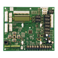
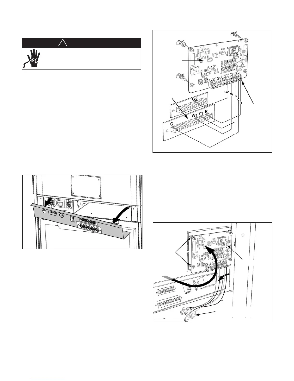
Figure 39: Connect Wires to the RCN Terminals and snap
the plastic standoffs onto Board
3. Snap the plastic standoffs into the RCN as illustrated
in Figure 39.
4. Reach inside the area behind the removed terminal
strip cover and up behind the knockout. Align the
standoffs on the board with the provided standoff
holes on the knockout plate and snap the standoffs
into the holes (Figure 40).
Figure 40: Secure the RCN to the Unit with the Standoffs
5. Connect the RCN wires with connectors to the low
voltage terminals and reinstall the terminal strip
cover.
Installing the (Optional) Remote Control
Node (RCN) For Use With The Optional
Wireless Thermostat
1. Remove the panel with the low voltage terminal
strip by removing two (2) screws at the front of the
cover and three (3) located on the underside. (Figure
38). The wires connected to the manual fan speed
switch may be removed for easier access.
Note: There are two methods for installing the RCN
to the unit. The RCN mounts on the back of the bezel
(blank control pad) and this assembly snaps into
the knockout on the face of the unit. This method
is not recommended since future replacement is
more difcult. The preferred method for a new unit
installation is illustrated below (Figures 38 – 40).
Figure 38: Remove the Cover Plate with the Low Voltage
Terminal Strip
2. Connect the provided wiring to the RCN terminals
as shown in Figure 39.
RCN
Plastic
Standoffs
(4)
RCN to Low Voltage
Terminal Connectors
RCN Terminals
Terminals
on Back of
Low Voltage
Terminal Strip
Plastic Standoffs (4)
Remote Control
Node (RCN)
DANGER
Disconnect all electrical power before servicing unit.
Electrical shock will cause severe injury or death.
!
 Loading...