Page 22 of 48 / IM 986-2
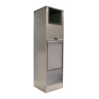
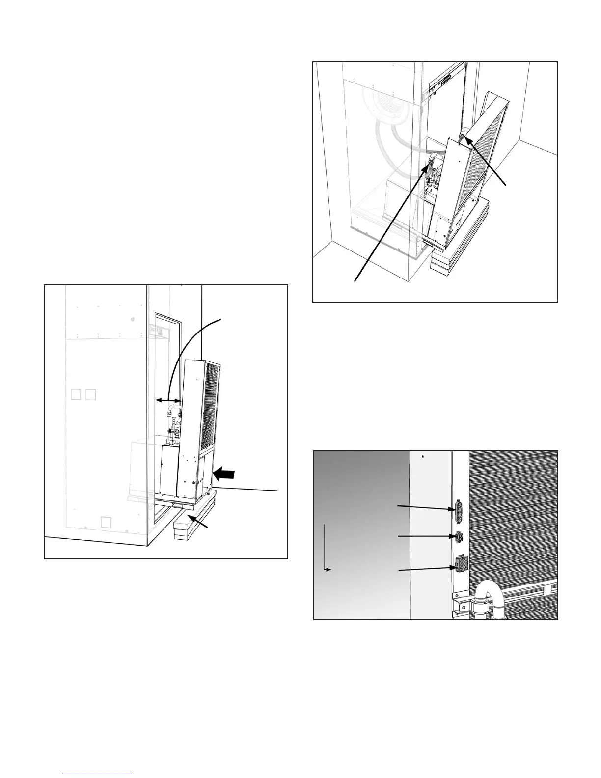
Figure 36: Slide Chassis into Cabinet Leaving a 10" Gap
for Clearance to Make Flexible Hose Connections
Making Cabinet to Chassis Wiring
Connections
1. Locate the wires and plugs in the upper fan section
of the unit that connect to the unit chassis.
2. Plug in the wires from the top cabinet section into
the proper molex connectors on the chassis (Figure 37).
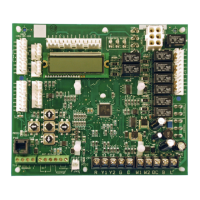
Figure 37: Plug unit component wiring from the top cabinet
section into the proper connectors on the chassis (Unit Size
021-036 Chassis Shown)
2. Push the chassis into the cabinet until it makes
contact with the stops on the rails at the rear of the
cabinet.
Note: Be sure there are no kinks and that the
stainless steel braided hoses do not come in contact
with and vibrate on chassis and cause noise. Also be
sure not to pinch wires between cabinet and chassis
when inserting chassis.
Installing Unit Chassis
1. Thread the MPT adapters removed from the swivel
ends of the exible hoses onto the chassis FPT
supply and return pipe connections. Using two
crescent wrenches, one to hold the chassis pipe
connection and the second on the adapter tting,
tighten the connections.
2. Install the chassis by sliding it into the cabinet
opening until the chassis support rails sit on the
cabinet rails. Slide the chassis into the cabinet
until there is approximately a 10" space between
the chassis coil and the cabinet. This will allow
adequate clearance to connect the exible hoses to
the chassis coil. For safety, place a 6" high block
under the chassis rails to support the chassis as
shown in Figure 35.
Figure 35: Slide chassis partially into the unit cabinet
2. Thread the female swivel ends of the hoses on to
the water supply and return connections. Using two
crescent wrenches, one to hold the straight MPT
adapter and the second on the exible hose swivel,
tighten the connections. (Figure 36).
Approximately
10" gap to
make hose
connections
6" high blocks to
support chassis
Supply
Connection
Return Connection
Main Power Connector
Note: On unit sizes
009-018 the Main
Power Receptacle and
Thermostat Connector
locations are switched
Fan Control
Connector
Thermostat Wiring
Connector
 Loading...