IM 986-2 / Page 19 of 48
10% 20% 30% 40% 50%
Cooling Capacity 0.9910 0.9510 – – –
Heating Capacity 0.9950 0.9600 – – –
Pressure Drop 1.0350 0.9600 – – –
10% 20% 30% 40% 50%
Cooling Capacity 0.9980 0.9720 – – –
Heating Capacity 0.9950 0.9700 – – –
Pressure Drop 1.0230 1.0570 – – –
10% 20% 30% 40% 50%
Cooling Capacity 0.9900 0.9800 0.9700 0.9600 0.9500
Heating Capacity 0.9870 0.9750 0.9620 0.9420 0.9300
Pressure Drop 1.0700 1.1500 1.2500 1.3700 1.4200
10% 20% 30% 40% 50%
Cooling Capacity 0.9950 0.9920 0.9870 0.9830 0.9790
Heating Capacity 0.9910 0.9820 0.9770 0.9690 0.9610
Pressure Drop 1.0700 1.1300 1.1800 1.2600 1.2800
Table 5: Antifreeze Correction Factors
Ethylene Glycol
Propylene Glycol
Methanol
Ethanol
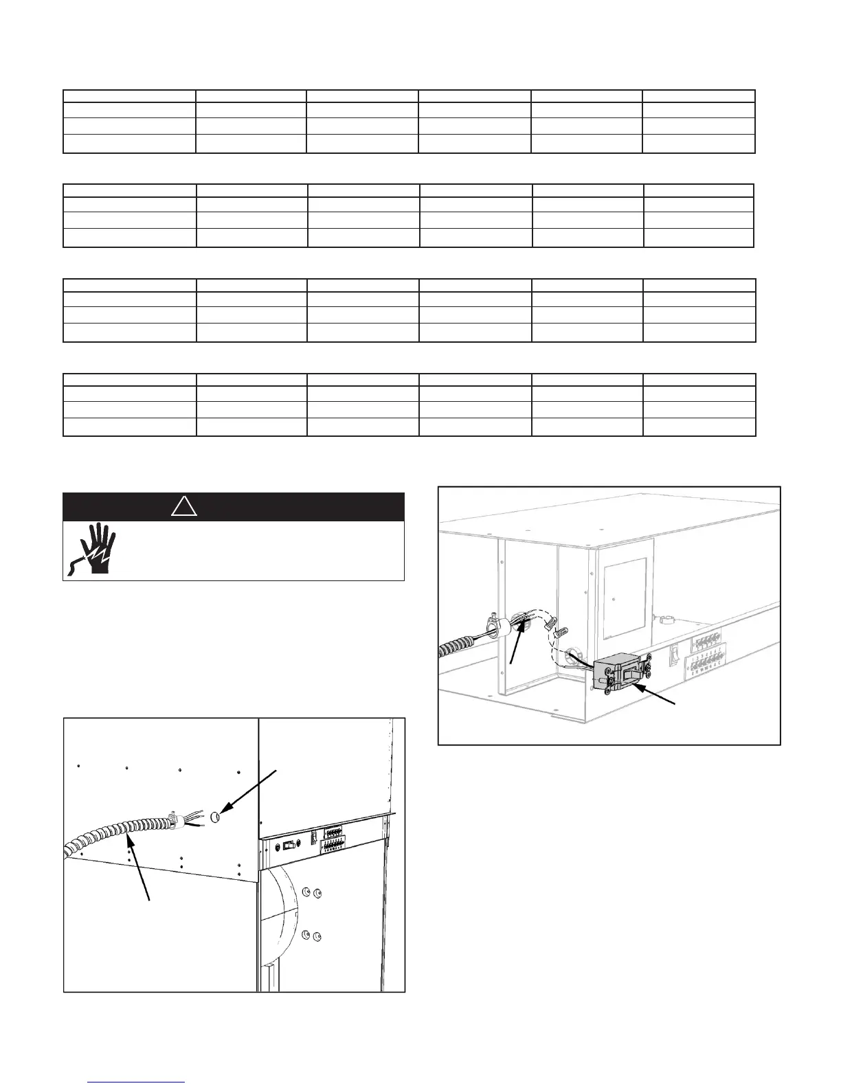
Power Wiring From Building to Unit
1. Locate the electrical power supply wiring from the
building and feed wiring through the 1/2" conduit
tting (strain relief) on the unit as shown in Figure
27 & 28, following local electrical codes and
regulations.
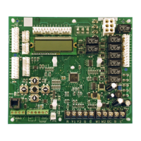
Figure 27: Supply Electric Wiring from Building to Unit
Figure 28: Wire to Unit Switch
2. If a remote wall-mounted thermostat is being used,
install a 24-volt thermostat wiring cable with at
least 6 wires from the unit low voltage terminal strip
(Figure 29) to the thermostat location.
3. If a wireless remote thermostat was ordered to
control the unit, it is recommended that the Remote
Control Node (RCN) be installed now.
Flexible Metal Conduit &
Strain Relief
1/2" Knockout for
Supply Wiring
DANGER
To avoid electrical shock, personal injury or death:
1. Installer must be qualied, experienced technician.
2. Disconnect power supply before installation to prevent
electrical shock and damage to equipment.
!
 Loading...