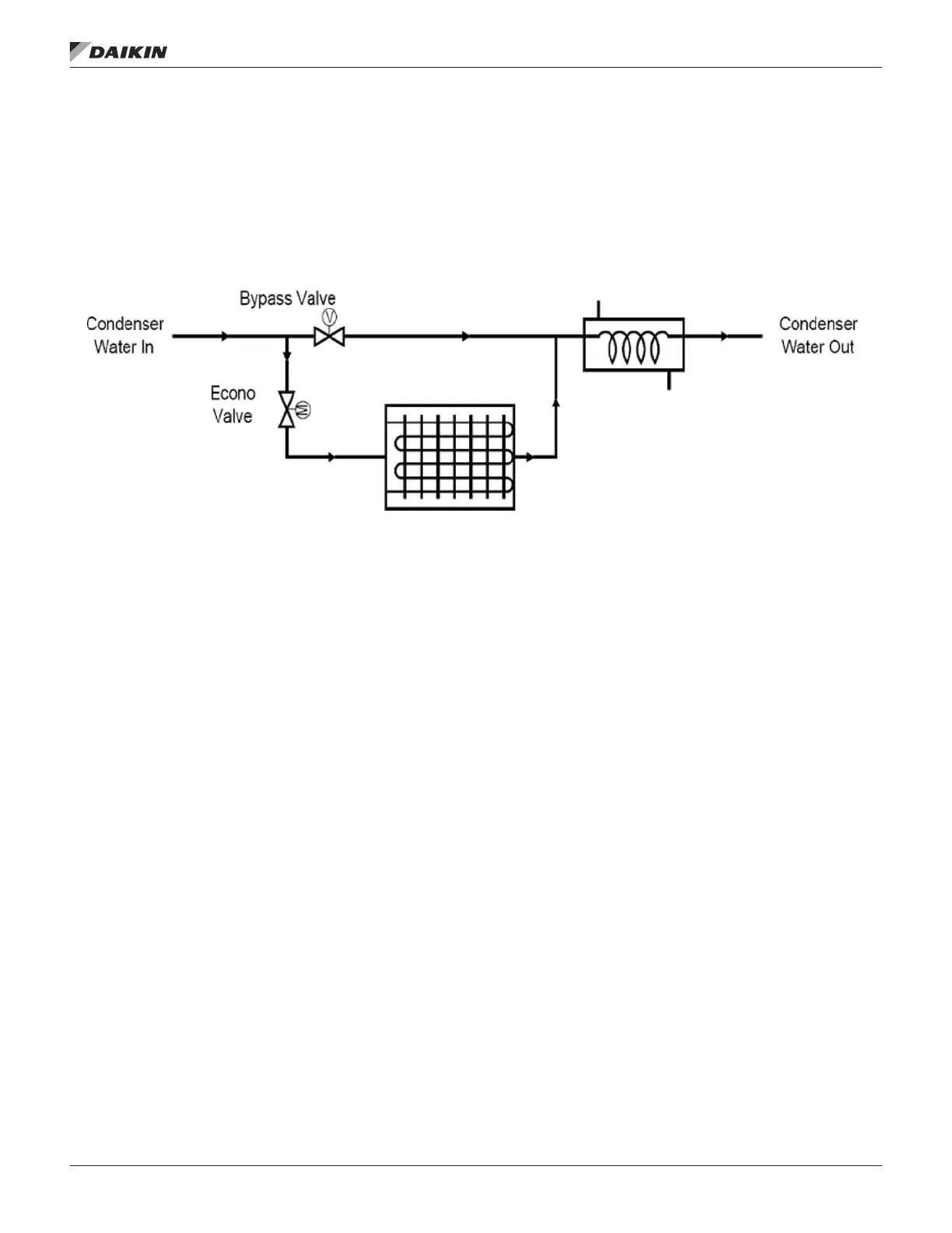
Bypass Valve Control
This section describes the operation of an analog output used
to control a valve that allows water to bypass a waterside
economizer and ow directly into a condenser.
When the bypass valve is closed, all water ows through the
waterside economizer before it ows through the condenser.
When the Bypass Valve is open, all water that ows into the
self-contained unit ows directly to the condenser without any
water going through the waterside economizer. There are two
different methods for controlling this valve; Slave Control and
Bypass Control.
Figure 15: Bypass Control Diagram
Slave Control
The bypass valve is linked electrically to the economizer valve
so that the bypass valve closes as the economizer opens.
This provides a nearly constant ow of water through the unit
regardless of the requirements of the economizer. When there
is no cooling required, the bypass valve will be open and the
waterside economizer valve is closed allowing water to ow
through the condenser. This valve control option can be used
in either a variable or constant pumping system.
Bypass Control
The bypass valve and waterside economizer valve are
independently controlled. The bypass valve to the condenser
is closed in all states except the Fan only, Mechanical cooling,
and Economizer. The bypass valve is open when mechanical
cooling is required and the water is not owing through the
waterside economizer. When the unit is OFF: Unoccupied,
both the bypass valve and the waterside economizer valve are
closed. No water is allowed to ow through the unit. This valve
control option is typically used in variable pumping system or a
constant pumping system with a bypass loop
Water Regulating Valve Control
In the Cooling state, the Water Regulating Valve stays at its last
commanded position when the last compressor is turned OFF.
When all compressors are OFF and a compressor needs to be
turned ON, the Water Regulating Valve must be driven open
long enough to prevent the compressor from being locked
out due to high pressure, but not so long that it is locked out
due to low pressure. The WRV Start Sequence described
below is used to make sure this is the case. This is required
when transitioning to the Cooling state from the Fan Only or
Economizer state.
In the Fan Only state, the Water Regulating Valve is normally
closed. The WRV Start Sequence described below is initiated
in the Fan Only state whenever all of the following are true:
• Cooling Status=Enabled or Off Ambient
• Airside Economizer operation is disabled or not installed
• Either of the following are true:
– Both of the following are true:
— Control Temperature Source is something other
than None
— Control Temperature > Occupied Cooling Setpoint
+ ½ the cooling dead band
– Both of the following are true:
— Control Temperature Source is set to None
— DAT > DAT Cooling Setpoint + ½ the cooling dead
band
operaTor’s guIde
www.DaikinApplied.com 107 OM 920-6 • MICROTECH UNIT CONTROLLER

 Loading...


