Compressor Control for RoofPak
VFD Compressor Operation
When an RTU is equipped with the VFD compressor option
there are two compressor circuits, one VFD controlled
compressor in circuit #2 with up to 3 xed speed compressors
in circuit #1 depending on unit model. Circuit #2 (containing
the VFD compressor) is always the “lead” circuit. The VFD
compressor is controlled via a 0-10VDC analog output signal
from the MT III controller that varies the VFD frequency
between 25rps (0VDC) and 100rps (10VDC). The minimum
and maximum rps (VDC) values actually used vary depending
on unit size, whether or not a xed speed compressor is
running and whether or not a special oil return boost mode of
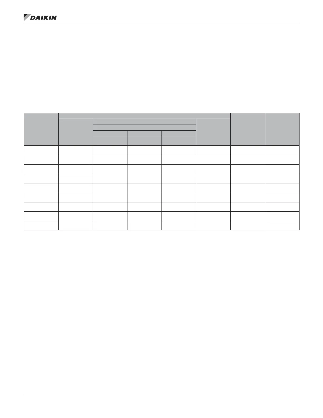
operation is active. The following table shows the relationship
between the minimums and maximums and unit size.
Table 51: VFD Compressor Size Range
RPS/RDT Unit
Model
VFD Modulation Range
LoOilBoostrps/
LoOilBoostV
HiOilBoostrps/
HiOilBoostV
VFDMinrps/
VFDMinV
VFD Max rps
VFD Comp Only
VFDMaxrps/
VFDMaxV
VFD and Fixed Comp(s) On
1 Fixed On 2 Fixed On 3 Fixed On
VFD1Maxrps/
VFD1MaxV
VFD2Maxrps/
VFD2MaxV
VFD3Maxrps/
VFD3MaxV
016
25 rps
0 Vdc
55 rps
4.0 V
NA
100 rps
10.0 V
70 rps
6.0 V
100 rps
10.0 V
021
25 rps
0 Vdc
70 rps
6.0 V
NA NA
100 rps
10.0 V
70 rps
6.0 V
100 rps
10.0 V
026
25 rps
0 Vdc
85 rps
8.0 V
NA NA
100 rps
10.0 V
70 rps
6.0 V
100 rps
10.0 V
031
25 rps
0 Vdc
70 rps
6.0 V
NA NA
100 rps
10.0 V
70 rps
6.0 V
100 rps
10.0 V
042
25 rps
0 Vdc
100 rps
10.0 V
95 rps
9.33 V
NA
100 rps
10.0 V
70 rps
6.0 V
100 rps
10.0 V
045
25 rps
0 Vdc
75 rps
6.7 V
75 rps
6.7 V
NA
75 rps
6.7 V
70 rps
6.0 V
75 rps
6.7 V
051
25 rps
0 Vdc
85 rps
8.0 V
85 rps
8.0 V
NA
85 rps
8.0 V
70 rps
6.0 V
85 rps
8.0 V
063
25 rps
0 Vdc
95 rps
9.33 V
95 rps
9.33 V
NA
95 rps
9.33 V
70 rps
6.0 V
95 rps
9.33 V
074
25 rps
0 Vdc
70 rps
6.0 V
50 rps
3.3 V
100 rps
10.0 V
75 rps
6.7 V
70 rps
6.0 V
100 rps
10.0 V
The basic compressor control sequence is to rst start the VFD
compressor and modulate it with a PI control loop to maintain
discharge temperature. When the VFD compressor is at its
maximum speed and more capacity is required, the available
xed compressor with the fewest run hour total is started (any
xed compressors on the VFD circuit are started rst) while
the VFD compressor is reduced to minimum speed. When the
VFD compressor is at its minimum speed and less capacity is
required the xed compressor with the highest run hour total
is stopped (any xed compressors on the circuit opposite the
VFD circuit are stopped rst) while the VFD compressor is
increased to maximum speed.
VFD Compressor Start Sequence
On a call for VFD compressor operation the VFD Enable
output (MCB DO3) is energized (on) and the 0-10VDC analog
control signal is set to 3.33VDC (50rps) for 10 seconds. During
this 10 second initial period the VFD compressor’s internal
logic ramps the compressor to 50rps (this aids in starting oil
circulation). After 10 seconds the VFD compressor control
signal begins modulating based on a PI loop to maintain the
cooling discharge setpoint.
NOTE: In addition to enabling VFD compressor operation
the VFD Enable output is used to energize a liquid
line drop solenoid on the VFD circuit and to turn on
auxiliary ventilation fans in the VFD compressor
enclosure.
Compressor Stage Up Transition
When the VFD compressor has been operating at maximum
capacity for the cooling stage time period (default 5 Minutes)
and more capacity is required, the xed compressor with the
fewest run hours is started (any xed speed compressors on
the same circuit as the VFD compressor is started rst). The
VFD compressor is held at is minimum value for 30 seconds.
operaTor’s guIde
www.DaikinApplied.com 113 OM 920-6 • MICROTECH UNIT CONTROLLER

 Loading...


