MPS Standard Condenser Fan Control
Standard Condenser Fan Control
Two, three or four condenser fans are provided. Two
condenser fans are provided on 15, 17.5, 20 and 25 ton units.
Three condenser fans are provided on 26, 30 and 35 ton units.
Four condenser fans are provided on 40 and 50 ton units. The
rst condenser fan is always turned ON when any compressor
is turned ON using compressor contactor auxiliary switches
external to the controller.
When two condenser fans are provided, the second condenser
fan (CondFanOutA) is turned ON when the OAT rises above
the Condenser Fan 1 Set Point. This fan is turned OFF when
the OAT drops below the setpoint by more than the Condenser
Fan Differential (Default = 5°F).
When three condenser fans are provided, the second
condenser fan is turned ON when the OAT rises above the
Condenser Fan 1 Set Point and the third fan is turned ON
when the OAT rises above the Condenser Fan 2 Set Point.
These fans are turned OFF when the OAT drops below that
corresponding setpoint by more than the Condenser Fan
Differential (Default = 5°F).
When four condenser fans are provided, there are two
different methods for control due to a redesign of the model
040 and 050.
When the “old” four condenser fan method is used (Condenser
Control=Standard Method 1) is used, two outputs (Condenser
Fan Output1 and Condenser Fan Output 2) on the controller
are used to provide three additional stages as shown in Table
58. The second through fourth stages are turned on when the
corresponding setpoint is exceeded by the OAT and turned
OFF when the OAT drops below the corresponding setpoint by
more than the Condenser Fan Differential (Default = 5°F).
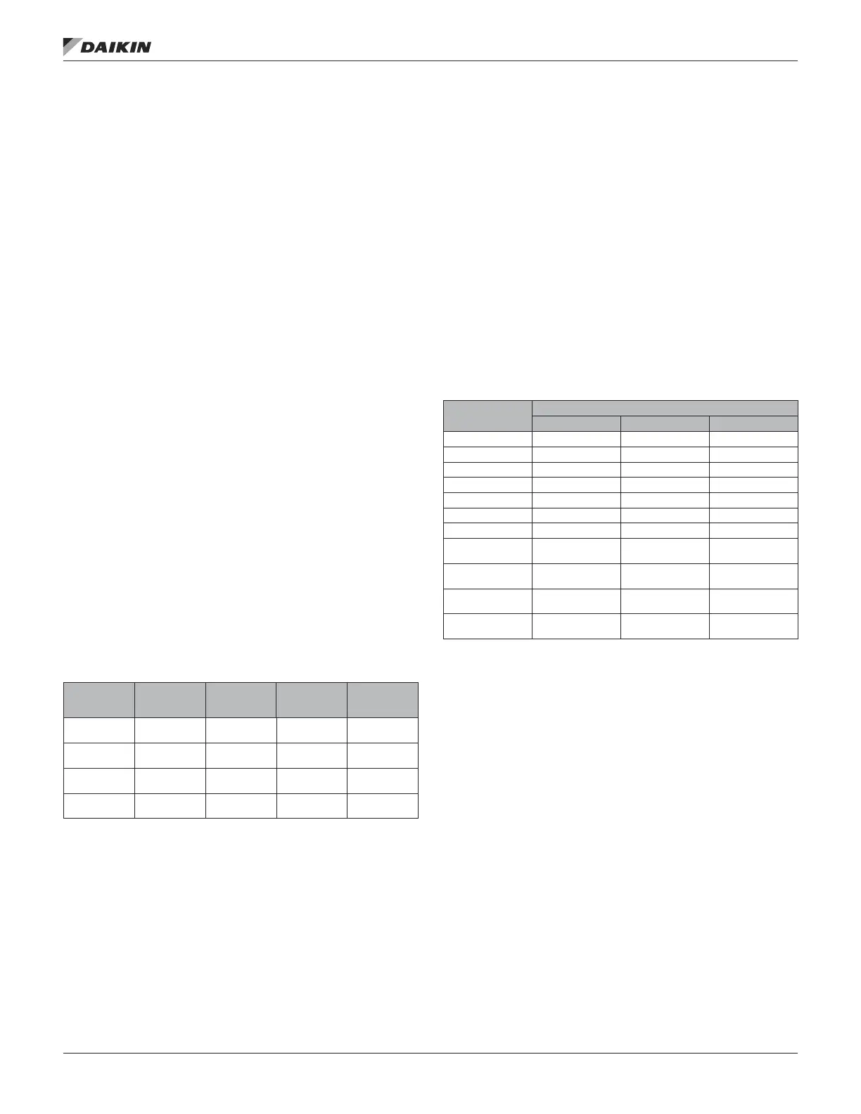
Table 58: Fan Staging
Operating
Fans (Stage)
Fan 1
(On with any
compressor)
Fan 2
(Cond Fan
Out A)
Fan 3 and 4
(Cond Fan
Out B)
On
Condition
1 On Off Off
Any
Comp On
2 On On Off
Cond Fan
1 Spt
3 On Off On
Cond Fan
2 Spt
4 On On On
Cond Fan
3 Spt
When the “new” four condenser fan method is used
(Condenser Control=Standard Method 2), the condenser
fan control is circuit specic. The rst fan on each circuit is
turned ON using compressor contactor auxiliary switches.
The second fan on each circuit is turned ON if a compressor
in the circuit is ON and the OAT is above the corresponding
condenser fan setpoint and is turned off when the OAT drops
below the corresponding setpoint by more than the Condenser
Fan Differential (Default = 5°F). Condense Fan 1 Setpoint
corresponds to the second fan on Circuit 1 and Condenser Fan
2 Setpoint corresponds to the second fan on Circuit 2.
The default condenser fan setpoints vary by unit size as
indicated in Table 59:
Table 59: CondenserFan Setpoints
Unit Size
Condenser Fan Setpoints
Cond Fan 1 Spt Cond Fan 2 Spt Cond Fan Spt
15 70°F/21.11°C — —
17 70°F/21.11°C — —
20 65°F/21.11°C — —
25 65°F/21.11°C — —
26 40°F/4.44°C 60°F/15.56°C —
30 40°F/4.44°C 60°F/15.56°C —
35 35°F/1.67°C 60°F/15.56°C —
40 (Cond Ctrl=Std
Method 1)
25°F/-3.89°C 45°F/7.22°C 60°F/15.56°C
50 (Cond Ctrl=Std
Method 1)
35°F/1.67°C 45°F/7.22°C 55°F/12.78°C
40 (Cond Ctrl=Std
Method 2)
70°F/21.11°C 70°F/21.11°C N/A
50 (Cond Ctrl=Std
Method 2)
70°F/21.11°C 70°F/21.11°C N/A
operaTor’s guIde
www.DaikinApplied.com 127 OM 920-6 • MICROTECH UNIT CONTROLLER

 Loading...


