Condenser Fan Control
RPS Units
There are up to four condenser fans per circuit. The rst fan on
each circuit is always turned on when any compressor on the
circuit is turned on through auxiliary switches on the compressor
contactors. The second two fans on each circuit (if applicable)
are controlled by outputs from the Main Controller. These are
controlled via Condenser Fan Output 1 and Condenser Fan
Output 2. The last fan on each circuit (if applicable) is controlled
by an external refrigerant pressure switch.
Condenser Fan Output 1 is turned ON when any
compressor on is on and the OAT rises above the
Condenser Fan A Set Point. Condenser Fan Output 1 is
turned OFF when all compressors are OFF or the OAT drops
below the Condenser Fan 1 Set Point by more than the
Condenser Fan Differential (Default = 5°F). External relays
allow operation of condenser fans associated with a specic
circuit only when a compressor on that circuit is ON.
Condenser Fan Output 2 is turned ON when any
compressor is ON and the OAT rises above the Condenser
Fan B Set Point. Condenser Fan Output 2 is turned OFF
when all compressors are OFF or the OAT drops below the
Condenser Fan 2 Set Point by more than the Condenser
Fan Differential (Default = 5°F). External relays allow
operation of condenser fans associated with a specic
circuit only when a compressor on that circuit is ON.
Condenser Fan Output 3 is turned ON when any
compressor is ON and the OAT rises above the Condenser
Fan 3 Set Point. Condenser Fan Output 3 is turned OFF
when all compressors are OFF or the OAT drops below the
Condenser Fan 3 Set Point by more than the Condenser Fan
Differential (Default = 5°F). External relays allow operation of
condenser fans associated with a specic circuit only when a
compressor on that circuit is ON.
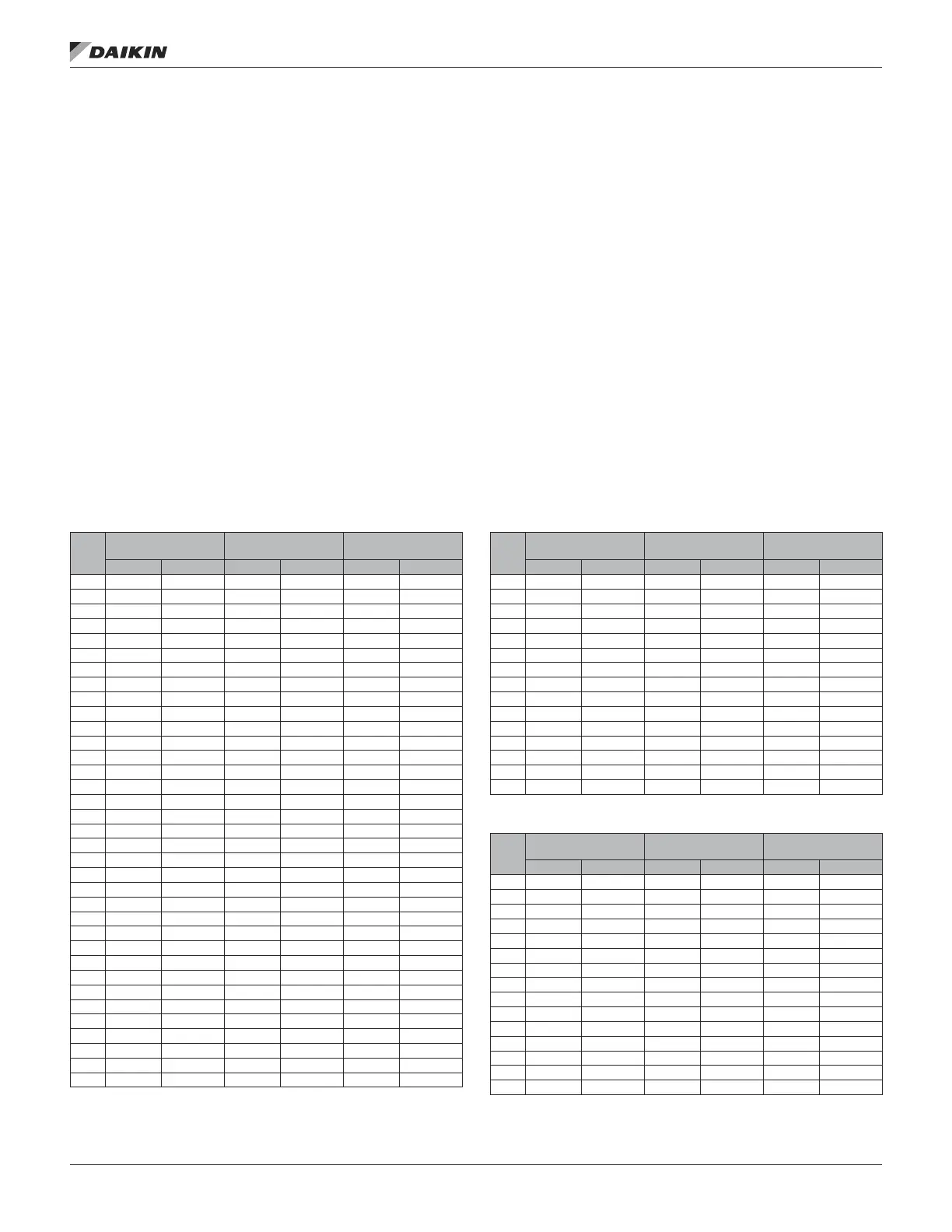
The Condenser Fan default setpoints vary by unit size according to the following tables:
Table 55: 410A Condenser Fan Setpoints
Unit
Size
CondFanOutput1
(MCB-DO7)
CondFanOutput2
(MCB-DO8)
PC13/PC231
Setpoint Differential Setpoint Differential Setpoint Differential
015 70 5 — — — —
016 75 5 — — — —
020 70 5 — — — —
021 75 5 — — — —
025 60 5 — — — —
026 70 5 — — — —
030 75 5 — — — —
031 75 5 — — — —
035 70 5 — — — —
040 65 5 — — — —
042 70 5 — — — —
045 65 5 — — — —
050 65 5 — — — —
051 70 5 — — — —
060 60 5 — — — —
062 70 5 — — — —
063 70 5 — — — —
068 70 5 — — — —
070 75 5 — — 90 35
071 75 5 — — 90 35
075 65 5 85 5 90 35
079 65 5 80 5 90 35
080 75 5 — — 90 35
081 75 5 — — 90 35
085 70 5 — — 90 35
090 60 5 85 5 90 35
091 60 5 85 5 90 35
100 60 5 85 5 90 35
101 60 5 85 5 90 35
105 50 5 80 5 90 35
110 65 5 90 5 90 35
120 65 5 85 5 90 35
125 65 5 85 5 90 35
130 60 5 85 5 90 35
140 55 5 80 5 90 35
Table 56: R22 Condenser Fan Setpoints
Unit
Size
CondFanOutput1
(MCB-DO7)
CondFanOutput2
(MCB-DO8)
CondFanOutput3
(MCB-DO6)
Setpoint Differential Setpoint Differential Setpoint Differential
015 60 5 — — — —
018 60 5 — — — —
020 60 5 — — — —
025 65 5 — — — —
030 65 5 — — — —
036 70 5 — — — —
040 65 5 — — — —
045 65 5 — — — —
050 60 5 — — — —
060 25 5 — — 70 5
070 40 5 — — 70 5
075 65 5 0 5 75 5
080 65 5 0 5 75 5
090 65 5 0 5 75 5
105 0 5 70 5 45 5
Table 57: R407C Condenser Fan Setpoints
Unit
Size
CondFanOutput1
(MCB-DO7)
CondFanOutput2
(MCB-DO8)
CondFanOutput3
(MCB-DO6)
Setpoint Differential Setpoint Differential Setpoint Differential
015 60 5 — — — —
018 0 5 — — — —
020 0 5 — — — —
025 65 5 — — — —
030 65 5 — — — —
036 65 5 — — — —
040 60 5 — — — —
045 55 5 — — — —
050 50 5 — — — —
060 15 5 — — 70 5
070 30 5 — — 70 5
075 65 5 0 5 75 5
080 65 5 0 5 75 5
090 50 5 0 5 75 5
105 0 5 70 5 35 5
OM 920-6 • MICROTECH UNIT CONTROLLER 126 www.DaikinApplied.com
operaTor’s guIde

 Loading...


