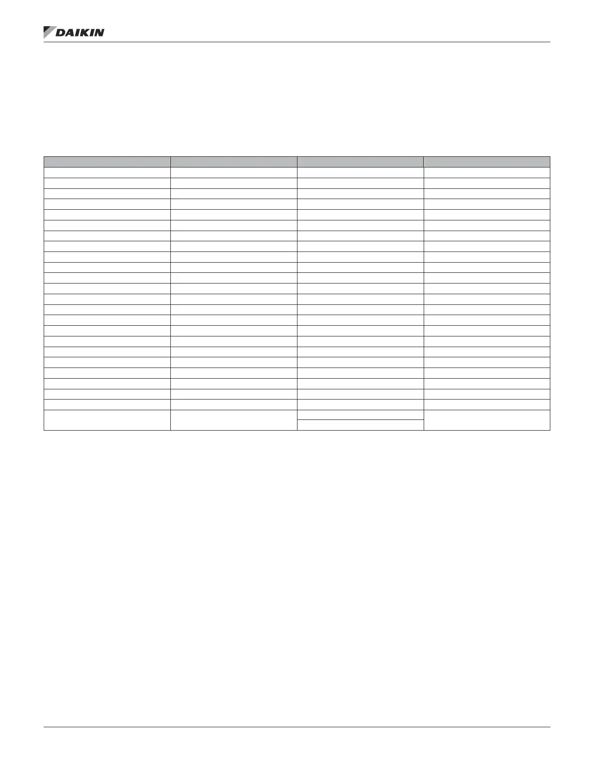
Energy Recovery Set-up
The Energy Recovery Set-up menu contains parameters that
relate to or are used to control the enthalpy wheel and exhaust
fan when a unit is equipped with an optional energy recovery
wheel system.
Table 30: Energy Recovery
Item Display Name Default Setting Range Password Level
Energy Rvcy= Yes Yes, No 4
ER Wheel= — On, Off 4
Wheel Speed= — 0–100% 4
Whl Spd Cmd= — 0–100% 4
ER LAT= — -50.0–200.0°F 4
ER EAT= — –50.0–200.0°F 4
Min ExhT Diff= 2.0°F 1.0–20.0°F 4
Max ExhT Diff= 6.0°F 1.0–20.0°F 4
ER Whl Stg Tm= 5min 1–100min 4
ER Whl Off Tm= 20min 1–100min 4
Rel Humidity= — 0–100% 4
Min Whl Spd 5% 0–100% 4
Intersect Pt= — -146.2.0–150.0°F 2
Fst Mgmt Meth= Timed Timed ExhAir 4
OA Fst Temp= -20.56°C -40.0 – 37.78°C 4
Defrost Time= 5min 0–60min 4
Defrst Period= 60min 0–1440min 4
Defrst On Tm= 1s 0–999s 2
Defrst Off Tm= 24s 0–999s 2
ER Whl Period= 30.0s 0–999.0s 2
ER Whl Gain= 1.0 0–100 2
ER Whl PAT= 30.0s 0–999.0s 2
ER Max Chg= 10% 0–100% 2
Capacity Limiting Yes
Yes
No
2
Menu desCrIpTIons
www.DaikinApplied.com 53 OM 920-6 • MICROTECH UNIT CONTROLLER

 Loading...


