Condenser Fan Operation for Variable Speed Compressor Low Ambient Option
(MPS 040 and 050 Only)
Daikin’s head pressure control operates by modulating the
motor speed of one condenser fan on the VFD compressor
refrigeration circuit in response to the condenser pressure.
VFD compressor refrigerant circuit contains a solenoid valve
that blocks refrigerant ow to half of the condenser coil, which
effectively removes 50% of the condenser surface from the
circuit for low load/low ambient conditions.
This option allows for mechanical cooling operation down to 0F
(-18C). The VFD option senses refrigerant head pressure and
varies the fan speed accordingly. When the pressure rises, the
SpeedTrol increases the speed of the fan, when the pressure
falls. SpeedTrol decreases the speed of the fan.
The VFD throttling range is 250 to 400 psig, xed, with a
corresponding fan speed range of 10Hz to 60Hz. The fan
motor is a three-phase motor, identical to the unit voltage
(208V to 575V) and is controlled by a variable frequency
drive. The variable frequency drive receives a signal from a
pressure transducer and varies the speed of the condenser fan
accordingly.
The SpeedTrol arrangement for VFD compressors is also
employing “Start-Stop control by Speed reference Level” in
which the VFD will stop the condenser fan motor under certain
conditions. If the head pressure were to fall below 250 PSIG
with the condenser fan operating at minimum speed of 10Hz
(possibly due to a low ambient or high wind condition) the
VFD will shut down the condenser fan. The VFD will restart
the condenser fan at 20 Hz if head pressure rises to a level
above 250 PSIG. In addition to modulating fan speed, a
refrigerant solenoid valve is included in circuit #1. Operation of
the solenoid valve is based on head pressure. If the average
condensing pressure falls below 250 PSIG (83F sat) for 60
seconds, the condenser solenoid valve closes, effectively
removing 50% of the condensing surface. If the averaging
condensing pressure rises above 350 PSIG (105F sat) for 60
seconds, the condenser solenoid valve is opened, activating
the entire condenser surface. The solenoid valve is disabled
above an outdoor ambient of 80F. The solenoid valve is in a
normally open conguration.
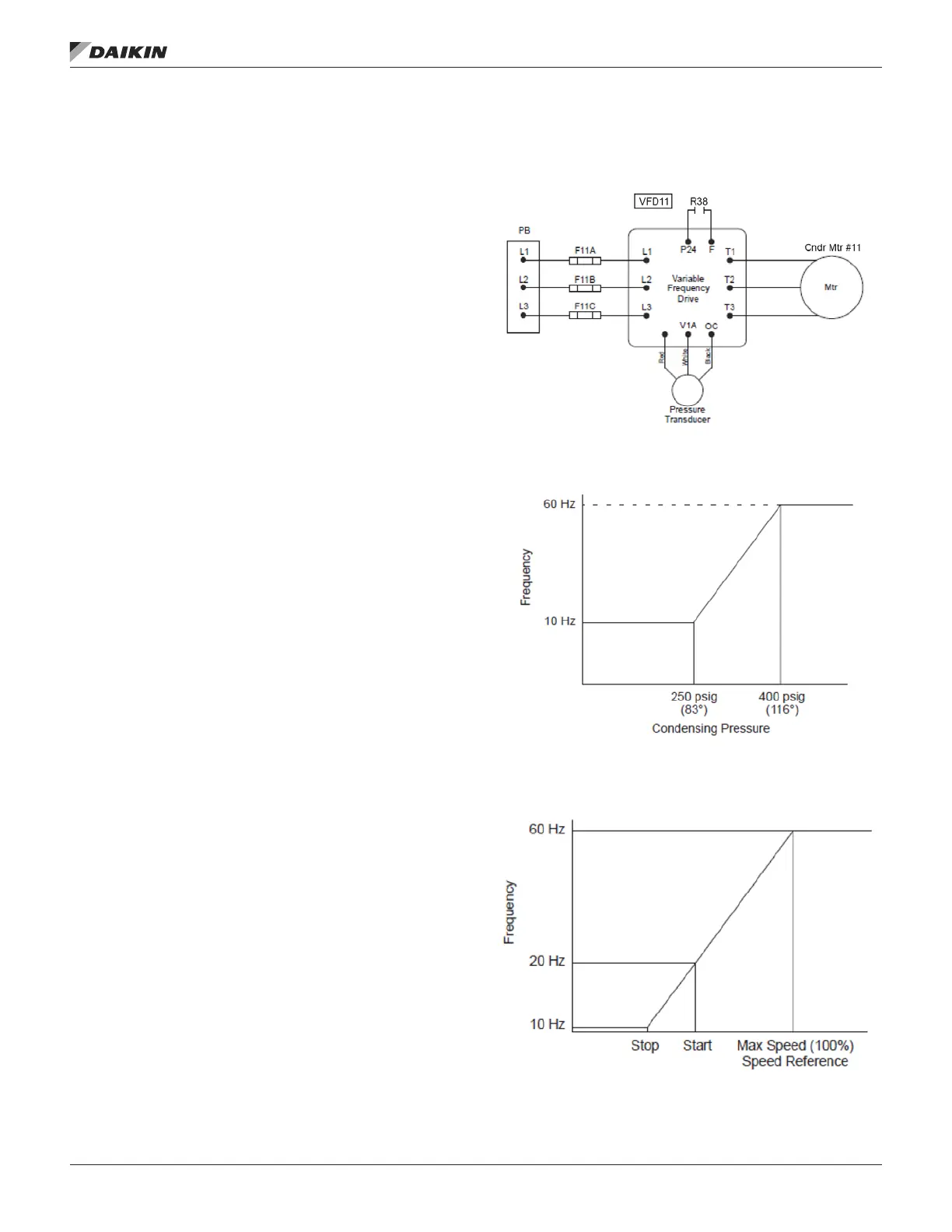
Refer to Figure 19 for wiring schematics of SpeedTrol.
Refer to Figure 20 and Figure 21 for SpeedTrol operating
characteristics.
Figure 19: R-410A Speedtrol
Figure 20: Speedtrol Operating Characteristics (for
Variable Speed Inverter Compressor Units)
Figure 21: Speedtrol Operating Characteristics (for
Variable Speed Inverter Compressor Units with Start-Stop
Control)
OM 920-6 • MICROTECH UNIT CONTROLLER 122 www.DaikinApplied.com
operaTor’s guIde

 Loading...


