Unit Conguration
Unit Conguration Setup Menu
After the main control board application software is loaded
into the MCB, it must be “congured” for the specic
control application. This consists of setting the value of 25
conguration variables within the MCB. These variables dene
things such as the type of cooling, number of compressors and
cooling stages and the type of heat. If all of these items are not
set appropriately for the specic unit, the unit will not function
properly. The correct settings for these parameters are dened
for a given unit by the unit “Software Conguration Code.”
The “Software Conguration Code” consists of a 29-character
string of numbers and letters. The code can be found on the
Unit Software Identication Label located on the back side of
the control panel door.
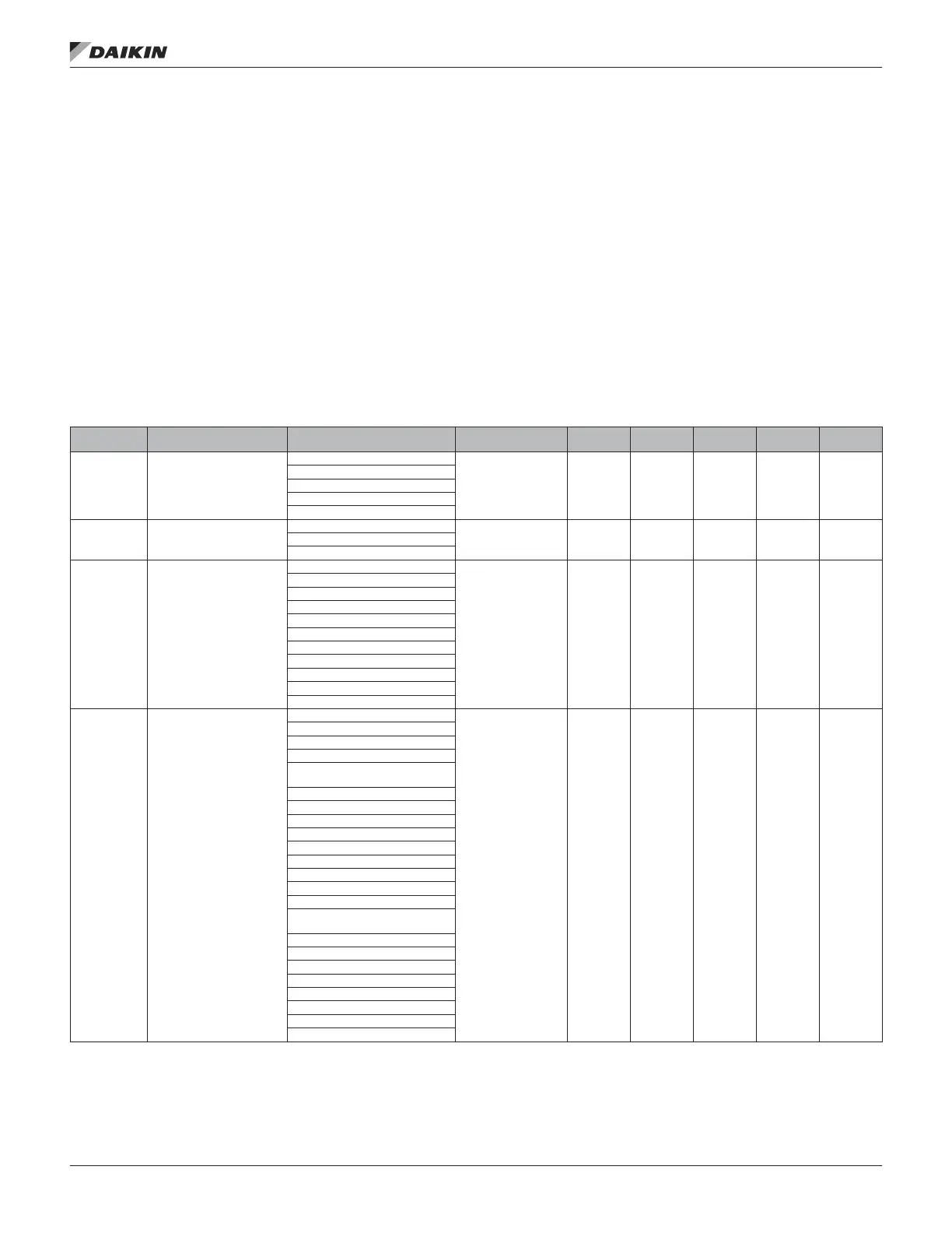
Table 50 lists the conguration code variables including the
position within the code, description of the parameter, and the
applicable settings for each. The default values are shown
in bold font. The unit is congured at the factory however
may also be congured in the eld by accessing the Unit
Conguration Menu. Once changes have been made to the
Unit Conguration Menu, the Apply Changes ag must be
changed from no to yes in order for the controller to recognize
the changes. Setting the Apply Changes ag to yes will
automatically rest the controller.
Table 50: Unit Conguration Menu
Conguration
Code Position
Description Values (Default in Bold) Special Condition RTU MPS DPS DPS_H SCU
1 Unit Type
0=Applied Rooftop (RTU)
● ● ● ● ●
1=Self-Contained (SCU)
2=Commercial Rooftop (MPS)
3=Rebel Cool Only (DPS)
4=Rebel Heat Pump (DPH)
2 Control Type
0=Zone Control
● ● ● ● ●1=DAT Control
2=1ZoneVAV
3 Cooling Type
0 = None
● ● ● ● ●
1=Standard Compressorized Clg
2=Chilled Water
3=F&BP
4=Variable Comp Circuit 1
5=Variable Comp Circuit 2
6=NA
7=NA)
8=NA)
9=Digital Comp 1 Circuit
10=Digital Comp 2 Circuits
4
Compressorized Cooling
Conguration
0=None
● ● ● ● ●
1=Generic Condenser
2=2Cmp/2Circ/3Stg
3=3Cmp/2Circ/4Stg
4=2Cmp/2Circ/2or6StgorVar
(6 stg if 7=2,3,4or5)
5=3Cmp/3Circ/3Stg_NoWRV
6=3Cmp/3Circ/3Stg_WRV
7=4Cmp/2Circ/4StgorVar
8=4Cmp/4Circ/4Stg_NoWRV
9=4Cmp/4Circ/4Stg_WRV
A=6Cmp/2Circ/6StgorVar
B=6Cmp/6Circ/6Stg_NoWRV
C=6Cmp/6Circ/6Stg_WRV
D=3Cmp/2Circ/5StgorVar
E=4Cmp/2Circ/5or8Stg)
(8 stg if 7=2,3,4or5)
F=8Cmp/4Circ/8Stg
G=8Cmp/8Circ/8Stg
H=6Cmp/3Circ/6Stg
I=Not Used
J=3 Cmp/3Circ/4Stg
K=Spare
L=1Var/1Circ
M=Var/1STD/1Circ
Menu desCrIpTIons
www.DaikinApplied.com 71 OM 920-6 • MICROTECH UNIT CONTROLLER

 Loading...


