Si04-306 Check
Service Diagnosis 133
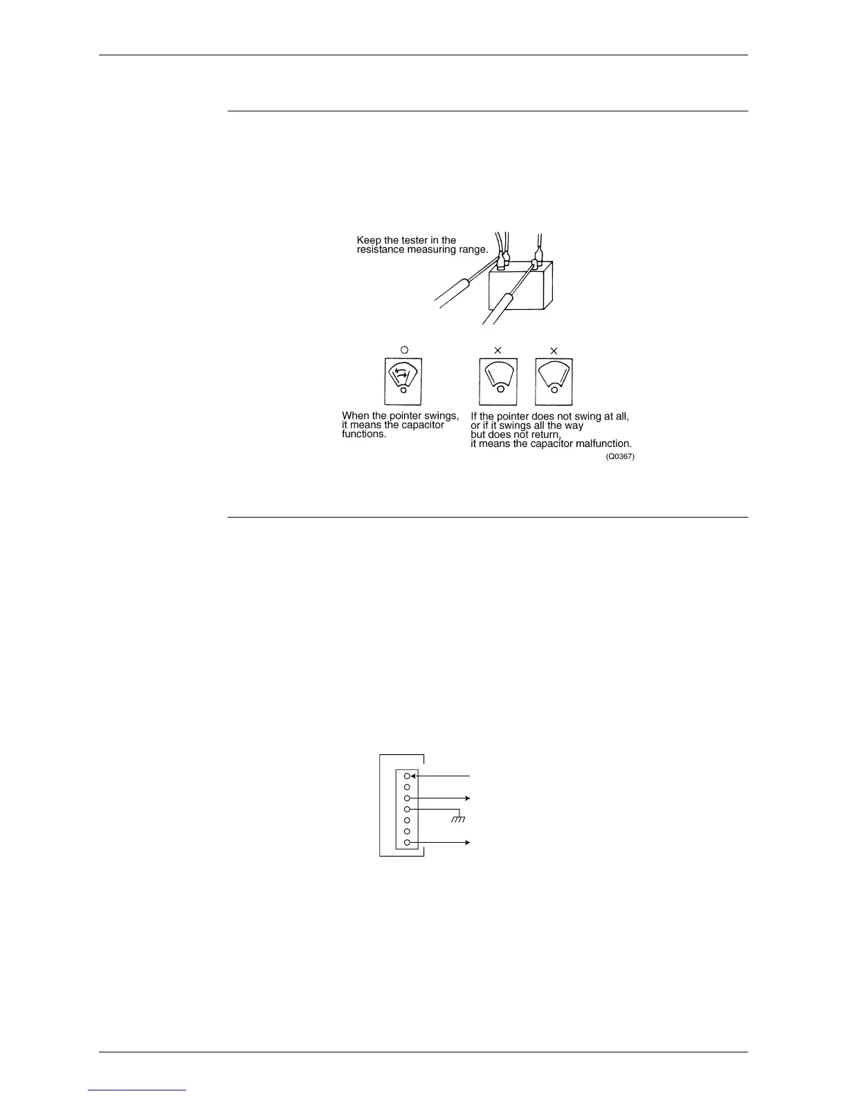
5.1.12 Main Circuit Electrolytic Capacitor Check
Check No.14
Checking the main circuit electrolytic capacitor
z
Never touch any live parts for at least 10 minutes after turning off the circuit breaker.
z
If unavoidably necessary to touch a live part, make sure there is no DC voltage using the
tester.
z
Check the continuity with the tester. Reverse the pins and make sure there is continuity.
5.1.13 Turning Speed Pulse Input on the Outdoor Unit PCB Check
Check No.15 <Propeller fan motor>
Make sure the voltage of 270±30V is being applied.
(1) Stop the operation first and then the power off, and disconnect the connector S70.
(2) Make sure there is about DC 270 V between pins 4 and 7.
(3) With the system and the power still off, reconnect the connector S70.
(4) Make a turn of the fan motor with a hand, and make sure the pulse (0-15 V) appears twice at
pins 1 and 4.
If the fuse is blown out, the outdoor-unit fan may also be in trouble. Check the fan too.
If the voltage in Step (2) is not applied, it means the PCB is defective. Replace the PCB.
If the pulse in Step (4) is not available, it means the Hall IC is defective. Replace the DC fan
motor.If there are both the voltage (2) and the pulse (4), replace the PCB.
∗
Propeller fan motor : S70
7
6
5
4
3
2
1
DC270V
S70
PCB
Turning speed pulse input (0-15 V)
15V
(R2859)
 Loading...