5 Installation
Installation and operation manual
10
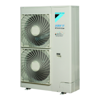
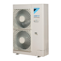
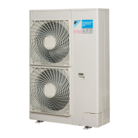
RXYSQ8~12TMY1B
VRV IV-S system air conditioner
4P400263-1F – 2017.02
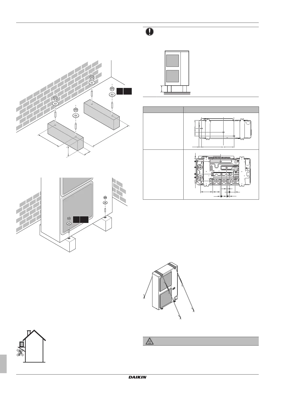
5.2 Mounting the outdoor unit
5.2.1 To provide the installation structure
Prepare 4 sets of anchor bolts, nuts and washers (field supply) as
follows:
(mm)
>150
620
8 HP: 350 (345~355)
10+12 HP: 490 (485~495)
4× M12
a
a Make sure not to cover the drain holes.
5.2.2 To install the outdoor unit
5.2.3 To provide drainage
▪ Make sure that condensation water can be evacuated properly.
▪ Install the unit on a base to make sure that there is a proper
drainage in order to avoid ice accumulation.
▪ Prepare a water drainage channel around the foundation to drain
waste water surrounding the unit.
▪ Avoid drain water flowing over the footpath, so that it does not
become slippery in case of ambient freezing temperatures.
▪ If you install the unit on a frame, install a waterproof plate within
150 mm of the bottom side of the unit in order to prevent the
invasion of water in the unit and to avoid the drain water dripping
(see the following illustration).
NOTICE
If drain holes of the outdoor unit are covered by a mounting
base or by floor surface, raise the unit to provide a free
space of more than 150mm under the outdoor unit.
Drain holes (dimensions in mm)
Model Bottom view (mm)
RXYSQ8
RXYSQ10+12
102
118
62
59
216
130
21
20
32
52
98
89
a
a Drain holes
5.2.4 To prevent the outdoor unit from falling
over
1 Prepare 2 cables as indicated in the following illustration (field
supply).
2 Place the 2 cables over the outdoor unit.
3 Insert a rubber sheet between the cables and the outdoor unit
to prevent the cable from scratching the paint (field supply).
4 Attach the cable’s ends. Tighten those ends.
5.3 Connecting the refrigerant piping
DANGER: RISK OF BURNING
 Loading...