5 Installation
Installation and operation manual
17
RXYSQ8~12TMY1B
VRV IV-S system air conditioner
4P400263-1F – 2017.02
NOTICE
In Europe, the greenhouse gas emissions of the total
refrigerant charge in the system (expressed as tonnes
CO
2
-equivalent) is used to determine the maintenance
intervals. Follow the applicable legislation.
Formula to calculate the greenhouse gas emissions:
GWP value of the refrigerant × Total refrigerant charge [in
kg] / 1000
2 Fix the label on the inside of the outdoor unit. There is a
dedicated place for it on the wiring diagram label.
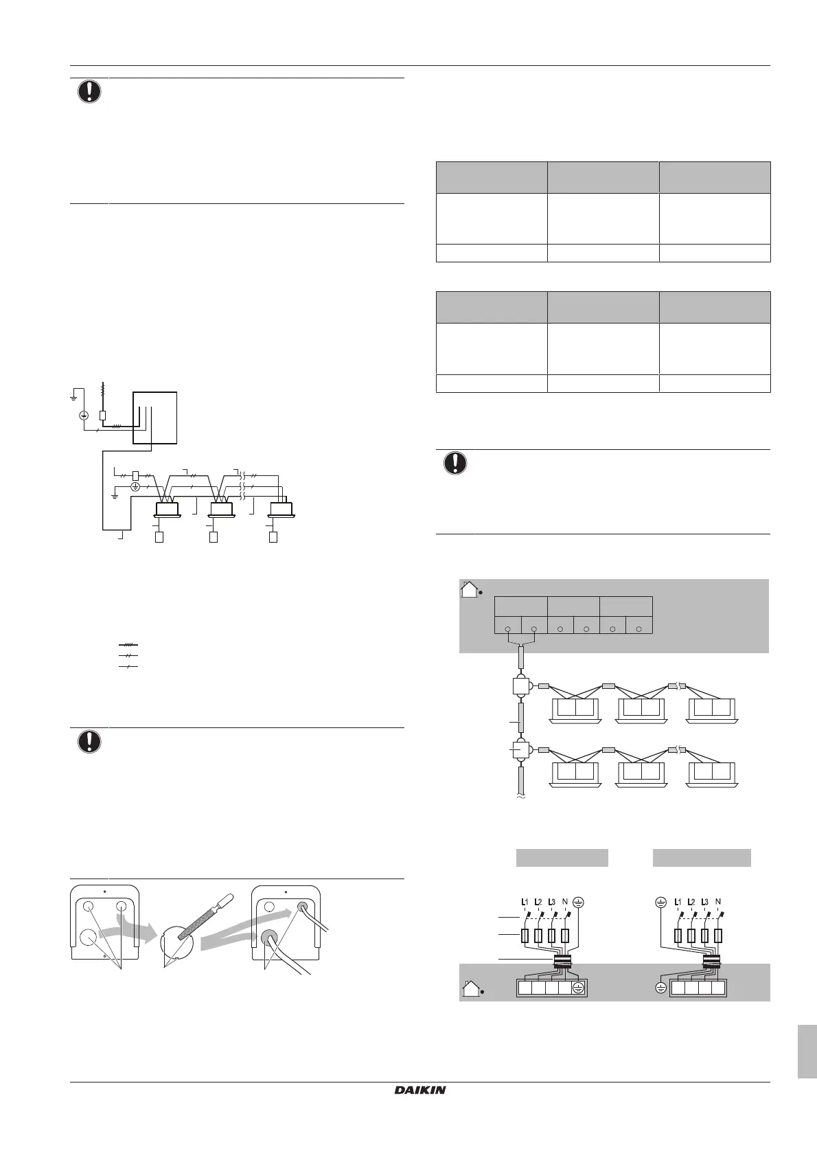
5.7 Connecting the electrical wiring
5.7.1 Field wiring: Overview
Field wiring consists of power supply (always including earth) and
indoor-outdoor communication (= transmission) wiring.
Example:
a
d
b
c
b g g
c
fffh
eee
a
h h h
h h
a Field power supply (with earth leakage protector)
b Main switch
c Earth connection
d Outdoor unit
e Indoor unit
f User interface
g Power supply wiring (sheathed cable) (230 V)
h Transmission wiring (sheathed cable) (16 V)
Power supply 3N~50Hz
Power supply 1~50Hz
Earth wiring
5.7.2 Guidelines when knocking out knockout
holes
NOTICE
Precautions when making knockout holes:
▪ Avoid damaging the casing.
▪ After making the knockout holes, we recommend you
remove the burrs and paint the edges and areas
around the edges using repair paint to prevent rusting.
▪ When passing electrical wiring through the knockout
holes, wrap the wiring with protective tape to prevent
damage.
a Knockout hole
b Burr
c Sealant etc.
5.7.3 Guidelines when connecting the electrical
wiring
Tightening torques
In case of RXYSQ8:
Wiring Screw size Tightening torque
(N•m)
Power supply wiring
(power supply +
shielded ground)
M5 2.2~2.7
Transmission wiring M3 0.8~0.97
In case of RXYSQ10+12:
Wiring Screw size Tightening torque
(N•m)
Power supply wiring
(power supply +
shielded ground)
M8 5.5~7.3
Transmission wiring M3.5 0.8~0.97
5.7.4 To connect the electrical wiring on the
outdoor unit
NOTICE
▪ Follow the wiring diagram (delivered with the unit,
located at the inside of the service cover).
▪ Make sure the electrical wiring does NOT obstruct
proper reattachment of the service cover.
1 Remove the service cover.
2 Connect the transmission wiring as follows:
F1 F2 F1 F2 F1 F2
F1 F2 F1 F2 F1 F2
a
b
X1M (A1P)
F1 Q2F2F1 Q1F2
TO MULTI
UNIT
TO OUT/DTO IN/D
a Use the conductor of sheathed wire (2 wire) (no polarity)
b Terminal board (field supply)
3 Connect the power supply as follows:
3N~50 Hz
380-415 V
L1 L2 L3
L1 L2 L3
N
8 HP 10+12 HP
3N~50 Hz
380-415 V
L1 L2 L3
L1 L2 L3
N
X1M X1M
a
b
c
a Earth leakage circuit breaker
b Fuse
c Power supply cable
4 Fix the cables (power supply and transmission wiring) with
cable ties.
 Loading...