5 Installation
Installation and operation manual
11
RXYSQ8~12TMY1B
VRV IV-S system air conditioner
4P400263-1F – 2017.02
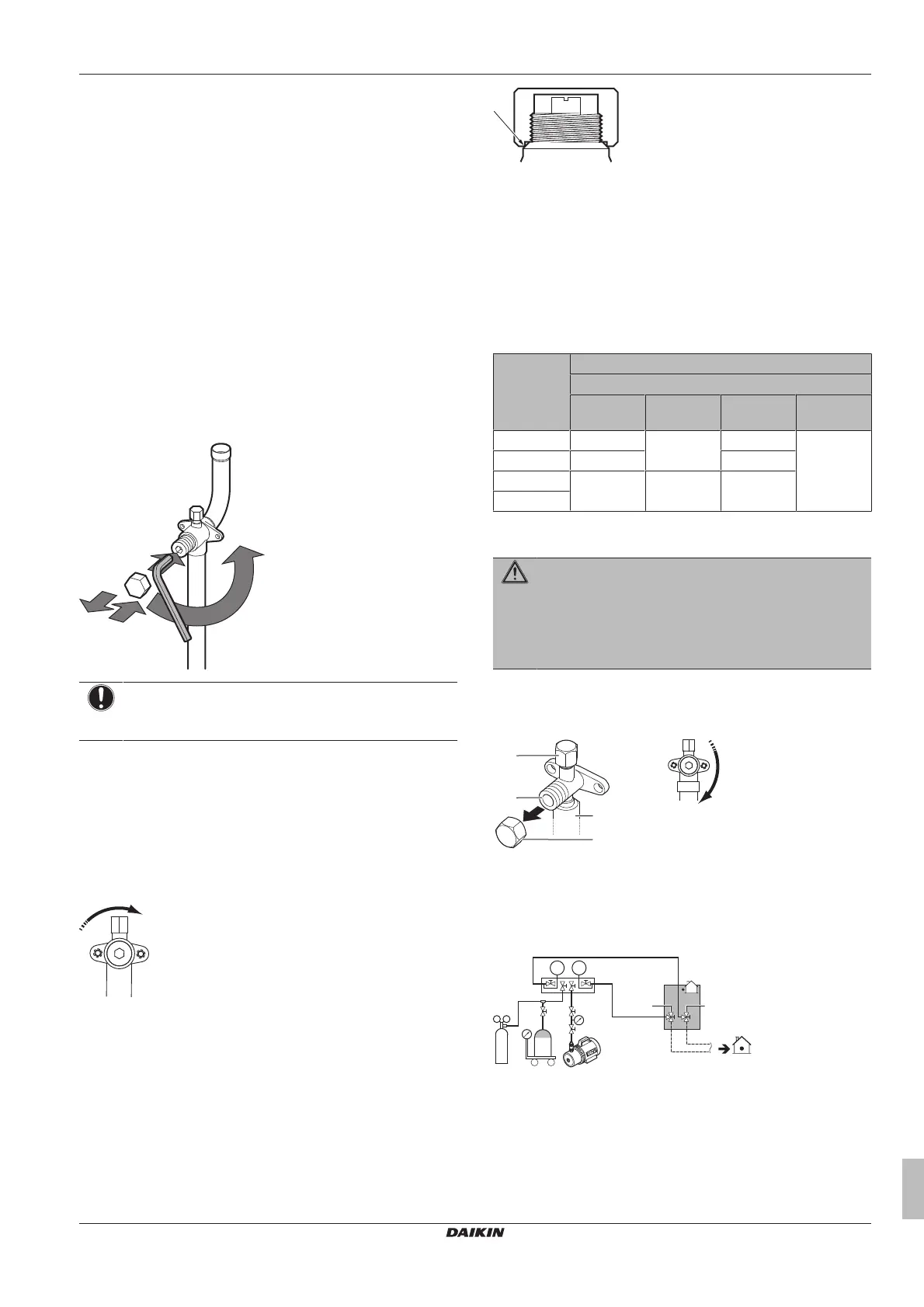
5.3.1 Using the stop valve and service port
To handle the stop valve
▪ Make sure to keep all stop valves open during operation.
▪ The stop valve is factory closed.
To open the stop valve
1 Remove the stop valve cover.
2 Insert a hexagon wrench into the stop valve and turn the stop
valve counterclockwise.
3 When the stop valve cannot be turned any further, stop turning.
Result: The valve is now open.
To fully open the Ø19.1 mm~Ø25.4 mm stop valve, turn the
hexagonal wrench until a torque between 27 and 33 N•m is
achieved.
Inadequate torque may cause leakage of refrigerant and breakage of
the stop valve cap.
NOTICE
Pay attention that mentioned torque range is applicable for
opening Ø19.1~Ø25.4mm stop valves only.
To close the stop valve
1 Remove the stop valve cover.
2 Insert a hexagon wrench into the stop valve and turn the stop
valve clockwise.
3 When the stop valve cannot be turned any further, stop turning.
Result: The valve is now closed.
Closing direction:
To handle the stop valve cover
▪ The stop valve cover is sealed where indicated by the arrow. Take
care not to damage it.
▪ After handling the stop valve, make sure to tighten the stop valve
cover securely. For the tightening torque, refer to the table below.
▪ Check for refrigerant leaks after tightening the stop valve cover.
To handle the service port
▪ Always use a charge hose equipped with a valve depressor pin,
since the service port is a Schrader type valve.
▪ After handling the service port, make sure to tighten the service
port cover securely. For the tightening torque, refer to the table
below.
▪ Check for refrigerant leaks after tightening the service port cover.
Tightening torques
Stop valve
size (mm)
Tightening torque N•m (turn clockwise to close)
Shaft
Valve body Hexagonal
wrench
Cap (valve
lid)
Service
port
Ø9.5 5.4~6.6 4mm 13.5~16.5 11.5~13.9
Ø12.7 8.1~9.9 18.0~22.0
Ø19.1 27.0~33.0 8mm 22.5~27.5
Ø25.4
5.3.2 To remove the pinched pipes
WARNING
Any gas or oil remaining inside the stop valve may blow off
the pinched piping.
Failure to observe the instructions in procedure below
properly may result in property damage or personal injury,
which may be serious depending on the circumstances.
Use the following procedure to remove the pinched piping:
1 Remove the valve cover and make sure that the stop valves are
fully closed.
a Service port and service port cover
b Stop valve
c Field piping connection
d Stop valve cover
2 Connect the vacuuming/recovery unit through a manifold to the
service port of all stop valves.
a Pressure reducing valve
b Nitrogen
c Weighing scales
d Refrigerant R410A tank (siphon system)
e Vacuum pump
f Liquid line stop valve
g Gas line stop valve
A Valve A
B Valve B
 Loading...