6 Configuration
Installation and operation manual
19
RXYSQ8~12TMY1B
VRV IV-S system air conditioner
4P400263-1F – 2017.02
6.1 Making field settings
6.1.1 About making field settings
To configure the heat pump system, you must give input to the
outdoor unit's main PCB (A1P). This involves the following field
setting components:
▪ Push buttons to give input to the PCB
▪ A display to read feedback from the PCB
Field settings are defined by their mode, setting and value. Example:
[2‑8]=4.
PC configurator
For VRV IV-S heat pump system it is alternatively possible to make
several commissioning field settings through a personal computer
interface (for this, option EKPCCAB is required). The installer can
prepare the configuration (off-site) on PC and afterwards upload the
configuration to the system.
See also: "6.1.9 To connect the PC configurator to the outdoor
unit"on page25.
Mode 1 and 2
Mode Description
Mode 1
(monitoring
settings)
Mode1 can be used to monitor the current
situation of the outdoor unit. Some field setting
contents can be monitored as well.
Mode 2
(field settings)
Mode2 is used to change the field settings of
the system. Consulting the current field setting
value and changing the current field setting
value is possible.
In general, normal operation can be resumed
without special intervention after changing field
settings.
Some field settings are used for special
operation (e.g., 1 time operation, recovery/
vacuuming setting, manual adding refrigerant
setting, etc.). In such a case, it is required to
abort the special operation before normal
operation can restart. It will be indicated in
below explanations.
6.1.2 To access the field setting components
See "5.1.1To open the outdoor unit"on page9.
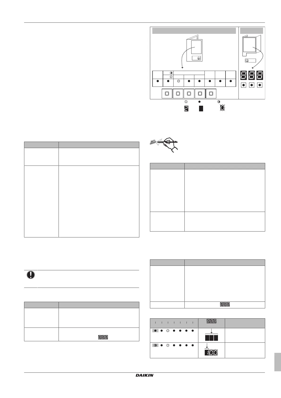
6.1.3 Field setting components
NOTICE
The DIP switches (DS1 and/or DS2 on A1P) are not used.
Do NOT change the factory setting.
The components to make field settings differ depending on the
model.
Model Field setting components
RXYSQ8 ▪ Push buttons (BS1~BS5)
▪ 7‑LEDs display (H1P~H7P)
▪ H8P: LED for indication during initialisation
RXYSQ10+12 ▪ Push buttons (BS1~BS3)
▪ 7‑segments display (
)
X1M
A1P
8 HP
BS2
SET
BS1
MODE
BS3
RETURN
BS4
TEST
BS5
RESET
H1P H2P H3P H4P H5P H6P H7P
MODE
TEST:
L.N.O.P.
DEMAND
C/H SELECT
HWL:
IND
MASTER
SLAVE
10+12 HP
A1P
X1M
BS1
BS2
BS3
H8P
MULTI
ON ( ) OFF ( ) Flashing ( )
ON (
) OFF ( ) Flashing ( )
Push buttons
Use the push buttons to make the field settings. Operate the push
buttons with an insulated stick (such as a closed ball-point pen) to
avoid touching of live parts.
The push buttons differ depending on the model.
Model Push buttons
RXYSQ8 BS1: MODE: For changing the set mode
BS2: SET: For field setting
BS3: RETURN: For field setting
BS4: TEST: For test operation
BS5: RESET: For resetting the address when
the wiring is changed or when an additional
indoor unit is installed
RXYSQ10+12 BS1: MODE: For changing the set mode
BS2: SET: For field setting
BS3: RETURN: For field setting
Display
The display gives feedback about the field settings, which are
defined as [Mode-Setting]=Value.
The display differs depending on the model.
Model Display
RXYSQ8 7‑LEDs display
H1P: Shows the mode
H2P~H7P: Shows the settings and values,
represented in binary code
H8P: NOT used for field settings, but used
during initialisation
RXYSQ10+12
7‑segments display (
)
Example:
H1P
H2P H3P H4P H5P H6P H7P
- + + + + +
[
H1P
32 16 8 4 2 1]
Description
(H1P OFF)
Default situation
(H1P flashing)
Mode 1
 Loading...