5 Installation
Installation and operation manual
9
RXYSQ8~12TMY1B
VRV IV-S system air conditioner
4P400263-1F – 2017.02
Indoor unit capacity
index
Piping outer diameter size (mm)
Gas pipe Liquid pipe
63~140 15.9 9.5
200 19.1
250 22.2
D: Piping between refrigerant branch kit and BP
unit
Total capacity index
of connected indoor
units
Piping outer diameter size (mm)
Gas pipe Liquid pipe
15~62 12.7 6.4
63~149 15.9 9.5
150~208 19.1
E: Piping between BP unit and RA DX indoor unit
Indoor unit capacity
index
Piping outer diameter size (mm)
Gas pipe Liquid pipe
15~42 9.5 6.4
50 12.7
60 9.5
71 15.9
4.2.4 To select refrigerant branch kits
For piping example, refer to "4.2.3 To select the piping size" on
page8.
Refnet joint at first branch (counting from outdoor unit)
When using refnet joints at the first branch counted from the outdoor
unit side, choose from the following table in accordance with the
capacity of the outdoor unit. Example: Refnet joint A→B‑1.
Outdoor unit capacity type
(HP)
Refrigerant branch kit
8+10 KHRQ22M29T9
12 KHRQ22M64T
Refnet joints at other branches
For refnet joints other than the first branch, select the proper branch
kit model based on the total capacity index of all indoor units
connected after the refrigerant branch. Example: Refnet joint
B‑1→C‑1.
Indoor unit capacity index Refrigerant branch kit
<200 KHRQ22M20T
200≤x<290 KHRQ22M29T9
290≤x<390 KHRQ22M64T
Refnet headers
Concerning refnet headers, choose from the following table in
accordance with the total capacity of all the indoor units connected
below the refnet header.
Indoor unit capacity index Refrigerant branch kit
<200 KHRQ22M29H
200≤x<290
290≤x<390 KHRQ22M64H
INFORMATION
Maximum 8 branches can be connected to a header.
4.3 Preparing electrical wiring
4.3.1 Safety device requirements
The power supply must be protected with the required safety
devices, i.e. a main switch, a slow blow fuse on each phase and an
earth leakage protector in accordance with the applicable legislation.
Selection and sizing of the wiring should be done in accordance with
the applicable legislation based on the information mentioned in the
table below.
Model Minimum circuit
ampacity
Recommended
fuses
RXYSQ8 18.5A 25A
RXYSQ10 22A 25A
RXYSQ12 24A 32A
For all models:
▪ Phase and frequency: 3N~50Hz
▪ Voltage: 380-415V
▪ Transmission line section:
Transmission wiring Vinyl cords with 0.75 to
1.25mm² sheath or cables
(2‑core wires)
Maximum wiring length
(= distance between outdoor
and furthest indoor unit)
300m
Total wiring length
(= distance between outdoor
and all indoors)
600m
If the total transmission wiring exceeds these limits, it may
result in communication error.
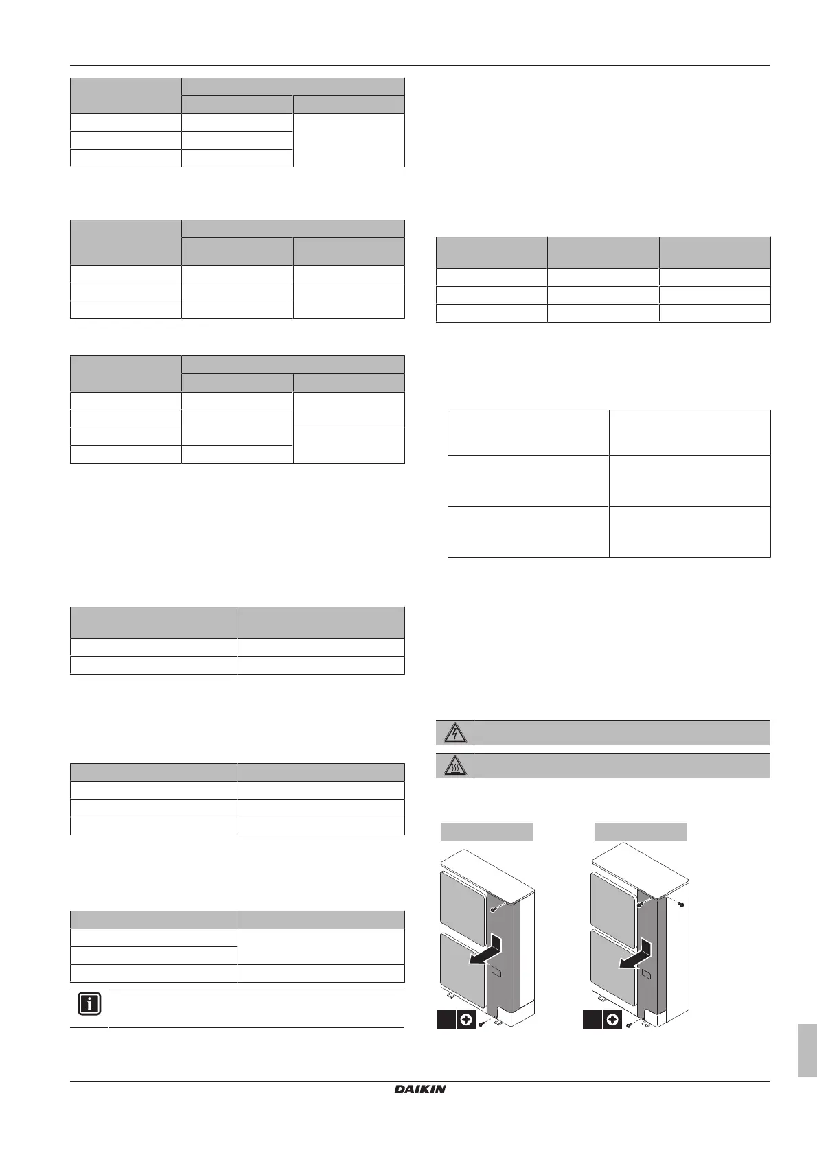
5 Installation
5.1 Opening the units
5.1.1 To open the outdoor unit
DANGER: RISK OF ELECTROCUTION
DANGER: RISK OF BURNING
 Loading...