9 Technical data
Installation and operation manual
31
RXYSQ8~12TMY1B
VRV IV-S system air conditioner
4P400263-1F – 2017.02
a,b,c,d,e Minimum service space between the unit and obstacles A, B, C, D and E
e
B
Maximum distance between the unit and the edge of obstacle E, in the direction of obstacle B
e
D
Maximum distance between the unit and the edge of obstacle E, in the direction of obstacle D
H
U
Height of the unit
H
B
,H
D
Height of obstacles B and D
1 Seal the bottom of the installation frame to prevent discharged air from flowing back to the suction side through the bottom of the unit.
2 Maximum two units can be installed.
Not allowed
Multiple rows of units (
)
See figure 2 on the inside of the front cover.
Stacked units (max. 2 levels) (
)
See figure 3 on the inside of the front cover.
A1=>A2 (A1) If there is danger of drainage dripping and freezing between the upper and lower units…
(A2) Then install a roof between the upper and lower units. Install the upper unit high enough above the lower unit to prevent ice buildup at the
upper unit's bottom plate.
B1=>B2 (B1) If there is no danger of drainage dripping and freezing between the upper and lower units…
(B2) Then it is not required to install a roof, but seal the gap between the upper and lower units to prevent discharged air from flowing back to the
suction side through the bottom of the unit.
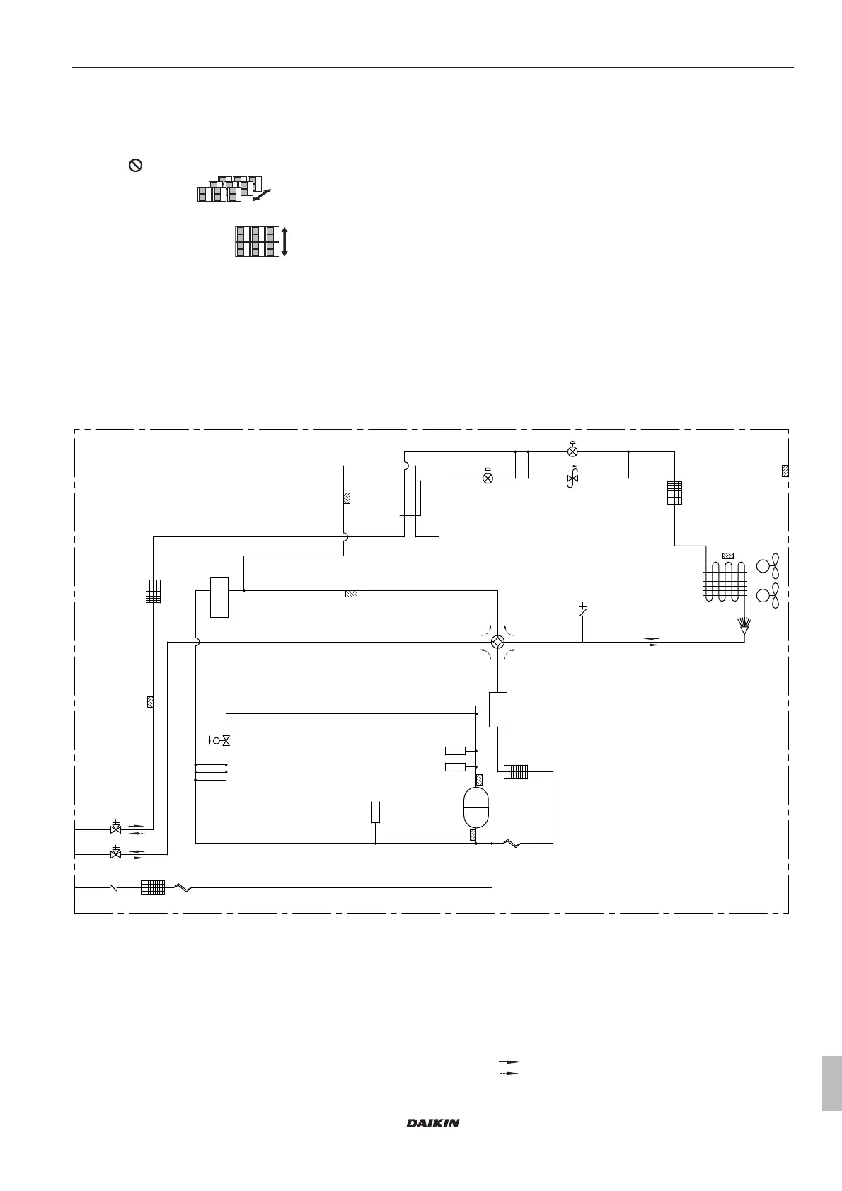
9.2 Piping diagram: Outdoor unit
RXYSQ8
R6T
a
b
k c j
c
c
c
d
e f
g
h
i
j
Y1S
S1NPL
S1NPH
S1PH
INV
M1C
Y3S
Y2E
Y1E
M1F
M2F
R7T
R5T
R2T
R3T
R4T
R1T
a Stop valve (gas)
b Stop valve (liquid)
c Filter (4×)
d Accumulator
e Subcool tube heat exchanger
f Pressure regulating valve
g Heat exchanger
h Service port (high pressure)
i Oil separator
j Capillary tube (2×)
k Service port (refrigerant charge)
M1C Compressor
M1F-M2F Fan motor
R1T Thermistor (air)
R2T Thermistor (suction 1)
R3T Thermistor (discharge)
R4T Thermistor (heat exchanger de-icer)
R5T Thermistor (subcool heat exchanger)
R6T Thermistor (liquid pipe)
R7T Thermistor (suction 2)
S1NPH High pressure sensor
S1NPL Low pressure sensor
S1PH High pressure switch
Y1E Electronic expansion valve (main)
Y2E Electronic expansion valve (subcool heat exchanger)
Y1S Solenoid valve
Y3S Solenoid valve (4‑way valve)
Heating
Cooling
 Loading...