10 About the system
Installation and operation manual
34
RXYSQ8~12TMY1B
VRV IV-S system air conditioner
4P400263-1F – 2017.02
Q1LD Leakage detection circuit (A1P)
Q1RP Phase reversal detect circuit (A1P)
R1T Thermistor (air)
R21T Thermistor (discharge)
R3T Thermistor (suction)
R4T Thermistor (heat exchanger liquid pipe)
R5T Thermistor (liquid pipe)
R6T Thermistor (subcool heat exchanger)
R7T Thermistor (heat exchanger de-icer)
R8T Thermistor (M1C body)
R1 Resistor (current limiting) (A3P)
R24 Resistor (current sensor) (A4P)
R313 Resistor (current sensor) (A3P)
R865, R867 Resistor (A3P)
S1NPH High pressure sensor
S1NPL Low pressure sensor
S1PH High pressure switch
SEG1~SEG3 7-segment display (A1P)
T1A Current sensor
V1R Power module (A3P) (A4P) (A5P)
V2R Power module (A3P)
X1A, X2A Connector (M1F)
X3A, X4A Connector (M2F)
X1M Terminal strip (power supply)
X1M Terminal strip (control) (A1P)
Y1E Electronic expansion valve (main)
Y2E Electronic expansion valve (subcool heat exchanger)
Y1S Solenoid valve (4‑way valve)
Y2S Solenoid valve
Z1C~Z4C Noise filter (ferrite core)
Z1F Noise filter (with surge absorber) (A2P)
For the user
10 About the system
The indoor unit part of VRV IV-S heat pump system can be used for
heating/cooling applications. The type of indoor unit which can be
used depends on the outdoor units series.
NOTICE
Do not use the system for other purposes. In order to avoid
any quality deterioration, do not use the unit for cooling
precision instruments, food, plants, animals or works of art.
NOTICE
For future modifications or expansions of your system:
A full overview of allowable combinations (for future
system extensions) is available in technical engineering
data and should be consulted. Contact your installer to
receive more information and professional advice.
INFORMATION
▪ Combination of VRVDX and RADX indoor units is not
allowed.
▪ Combination of RA DX and AHU indoor units is not
allowed.
▪ Combination of RADX and aircurtain indoor units is not
allowed.
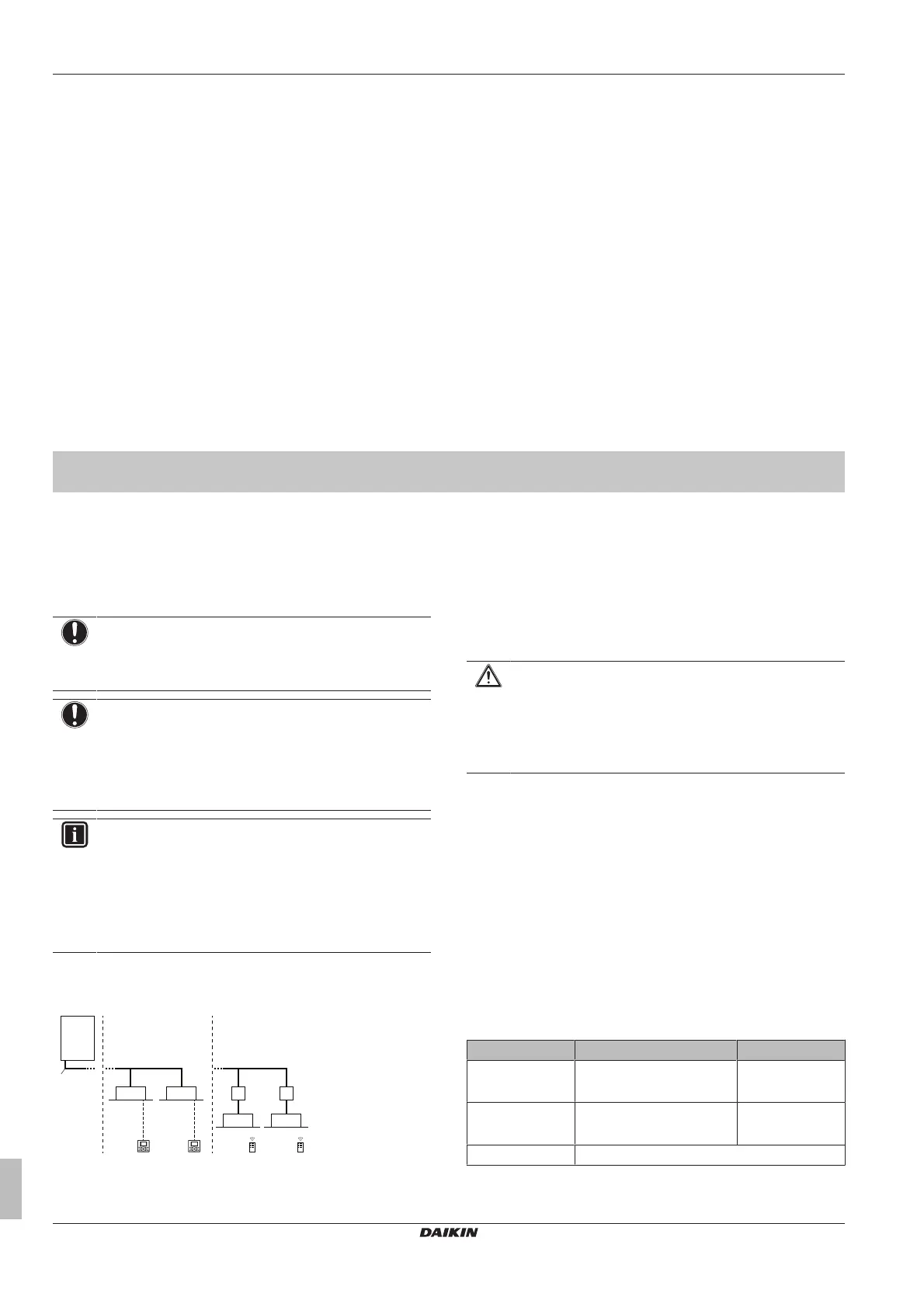
10.1 System layout
a VRV IV-S Heat pump outdoor unit
b Refrigerant piping
c VRV direct expansion (DX) indoor unit
d User interface (dedicated depending on indoor unit type)
e BP box (required to connect Residential Air (RA) or Sky Air
(SA) direct expansion (DX) indoor units)
f Residential Air (RA) direct expansion (DX) indoor units
g User interface (wireless, dedicated depending on indoor
unit type)
11 User interface
CAUTION
Never touch the internal parts of the controller.
Do not remove the front panel. Some parts inside are
dangerous to touch and appliance problems may happen.
For checking and adjusting the internal parts, contact your
dealer.
This operation manual will give a non-exhaustive overview of the
main functions of the system.
Detailed information on required actions to achieve certain functions
can be found in the dedicated installation and operation manual of
the indoor unit.
Refer to the operation manual of the installed user interface.
12 Operation
12.1 Operation range
Use the system in the following temperature and humidity ranges for
safe and effective operation.
Cooling Heating
Outdoor
temperature
–5~52°CDB –20~21°CDB
–20~15.5°CWB
Indoor
temperature
21~32°CDB
14~25°CWB
15~27°CDB
Indoor humidity ≤80%
(a)
 Loading...