Troubleshooting by Remote Controller
22
2.3 Self-diagnosis by Wireless
Remote Controller
If unit stops due to an error, the operation indicating LED
on the signal receiving part of indoor unit flashes.
The error code can be determined by following the
procedure described below. (The error code is displayed
when an operation error has occurred. In normal
condition, the error code of the last problem is displayed.)
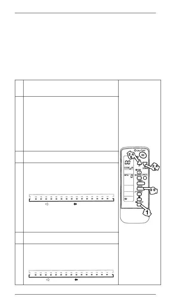
1
Press the INSPECTION/TEST button to select “inspection”. The
equipment enters the inspection mode. The “Unit” indication is
displayed and the Unit No. display shows flashing “0” indication.
2 Set the Unit No.
Press the UP or DOWN button and change the Unit No.
display until the buzzer (
∗
1) is generated from the indoor unit.
∗
1 Number of beeps
3 short beeps :
Conduct all of the following operations.
1 short beep : Conduct steps 3 and 4.
Continue the operation in step 4
until a buzzer remains ON. The
continuous buzzer indicates that
the error code is confirmed.
Continuous beep : No abnormality.
3 Press the MODE selector button.
The left “0” (upper digit) indication of the error code flashes.
4 Error code upper digit diagnosis
Press the UP or DOWN button and change the error code upper
digit until the error code matching buzzer (
∗
2) is generated.
The upper digit of the code changes as shown below
when the UP and DOWN buttons are pressed.
∗
2 Number of beeps
Continuous beep : Both upper and lower digits
matched. (Error code confirmed)
2 short beeps : Upper digit matched.
1 short beep : Lower digit matched.
5 Press the MODE selector button.
The right “0” (lower digit) indication of the error code flashes.
6 Error code lower digit diagnosis
Press the UP or DOWN button and change the error code lower digit
until the continuous error code matching buzzer (
∗
2) is generated.
The lower digit of the code changes as shown below
when the UP and DOWN buttons are pressed.
0ACEHFJLPU987654
"UP" button "DOWN" button
0123456789AHCJEF
"UP" button "DOWN" button
 Loading...