Troubleshooting by Indication on the Remote Controller
375
Master Unit Centralized Connector
Setting Table
The master unit centralized setting connector (CN1/X1A)
is mounted at the factory.
z To independently use a single unit of the intelligent
Touch Controller or a single unit of the centralized
remote controller, do not dismount the master unit
centralized setting connector (i.e., use the connector
with the factory setting unchanged).
z To independently use the schedule timer, insert an
independent-use setting connector.
No independent-use setting connector has been
mounted at the factory. Insert the connector, which is
attached to the casing of the master unit, in the PCB
(CN1/X1A).
(Independent-use connector = Master unit centralized
setting connector)
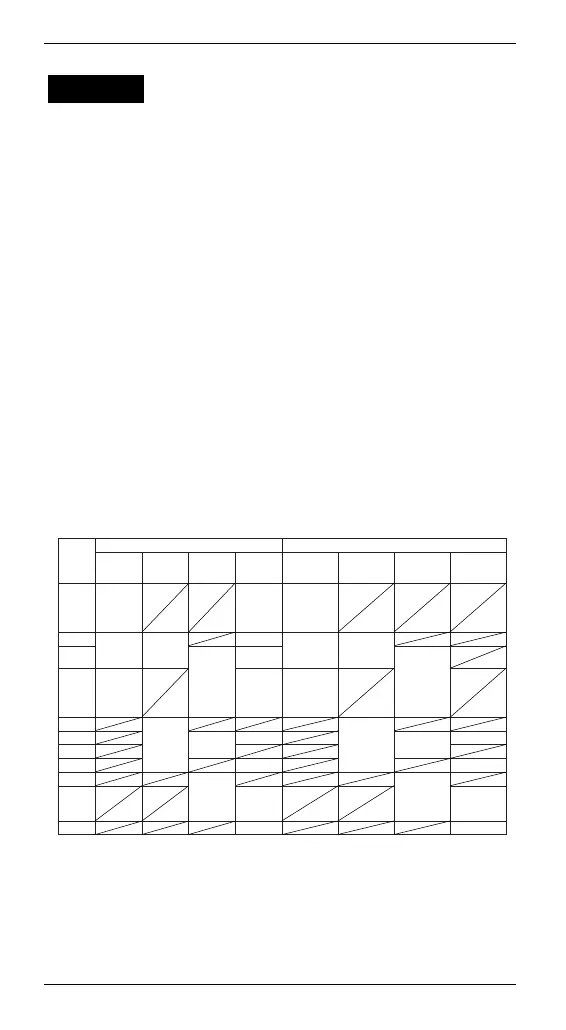
z To use two or more centralized controller in
combination, make settings according to the table
shown below.
CHECK 14
Centralized controller connection pattern Setting of master unit centralized setting connector (∗2)
× (∗1)
1 unit
1 unit
× (∗1)
Provided Not provided
× (∗1)
× (∗1)
1 unit Not provided
1 unit Not provided
1 unit Not provided
1 unit Provided
intelligent
Touch
Controller
Centralized
remote
controller
Unified
ON/OFF
controller
Schedule
timer
intelligent
Touch
Controller
Centralized
remote
controller
Unified
ON/OFF
controller
Schedule
timer
Only a
single unit:
"Provided",
Others: "Not
provided"
Only a
single unit:
"Provided",
Others: "Not
provided"
All "Not
provided"
Only a
single unit:
"Provided",
Others: "Not
provided"
All "Not
provided"
Only a
single unit:
"Provided",
Others: "Not
provided"
1 to 16
units
1 to 16
units
1 to 8
units
1 to 4
units
1 to 2
units
1 to 2
units
Pattern
(1)
(2)
(3)
(4)
(5)
(6)
(7)
(8)
(9)
(10)
(11)
 Loading...