Electrical Connections
EI.65.D4.02
11
4. ELECTRICAL CONNECTIONS
This chapter provides a general overview of the electrical connections to the
ECL 2000. Detailed information about wiring of individual heating systems (ap-
plications) is provided in Chapter 5 starting on page 21.
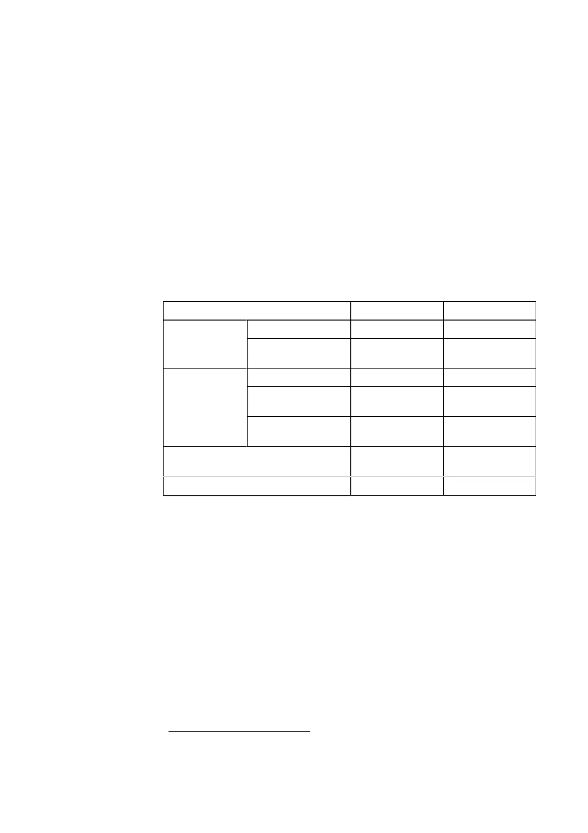
4.1 ECL 2000 Types
As previously mentioned, two types of the ECL 2000 controller are available:
Type 1 and Type 2. The table below summarizes the differences in I/O configura-
tion between the two types.
Type 1 Type 2
Inputs
Pt 1000 7 7
Pt 1000, 0-10 V, pulse
or digital
24
Outputs
Relay (pump control) 3 3
3-point control (motor
valve control)
2 –
0-10 V (motor valve
control)
–3
Power supply
230 V AC
24 V AC
24 V AC
Pre-programmed applications
1
1 – 14 1 – 17
4.2 Connecting Cables to the ECL 2000
Cables are connected to the controller via two terminal blocks with screw termi-
nals (see Figure 10 on page 12).
A maximum of 3 x 1.5 mm
2
or corresponding wires can be connected to each ter-
minal. The terminal blocks are coded to prevent terminal blocks with mains volt-
age being connected to sensor terminals.
If more than 3 wires need to be connected to the same terminal, use the loop ter-
minals provided on the inside of the base plate (see Figure 10, page 12).
1
See page 36 for an overview of ECL 2000 applications
 Loading...