Introduction
EI.65.D4.02
1
1. INTRODUCTION
1.1 About This Manual
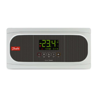
ECL 2000 is available in two versions with different input/output configurations.
ECL 2000 Type 1 has 14 preprogrammed applications designed as 14 standard
system setups and type 2 has 17 preprogrammed applications.
The purpose of this installation manual is:
• To describe how to install and configure ECL 2000, and
• To provide the installer with system and wiring diagrams for each application
and type.
For a detailed description of regulation and setting parameters, see ECL 2000
User’s Guide, ref. [2].
1.2 Overview of Components
The list below provides an overview of the various ECL 2000 products including
code numbers. In the following chapters, the individual products and their instal-
lation are described. See also data sheet on ECL 2000, ref. [4].
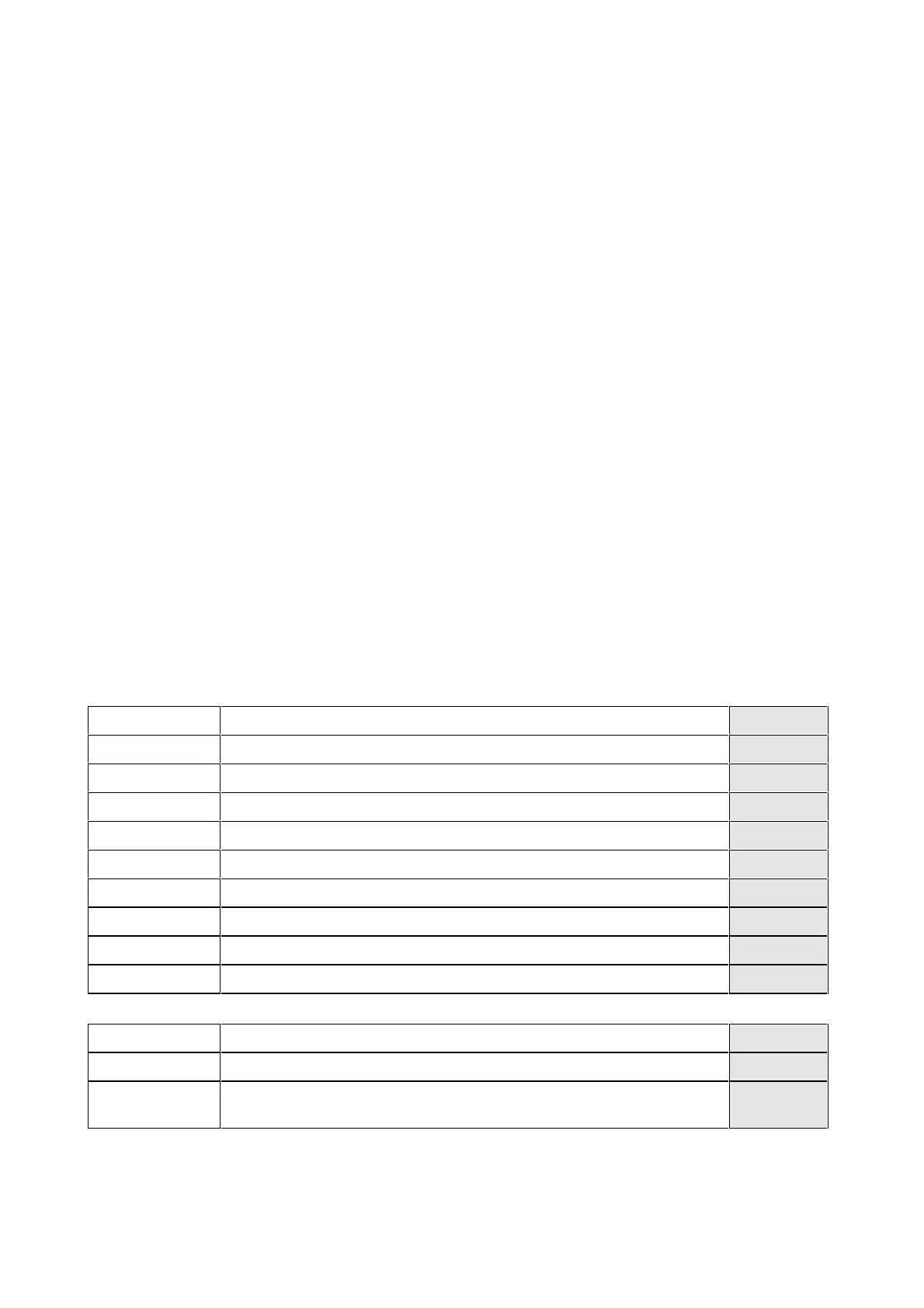
Controllers Description Code No.
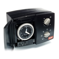
ECL 2000 Temperature controller 230V AC. Type 1 without LON communication 087B8000
ECL 2000 Temperature controller 230V AC. Type 1 with LON TP/XF-78 087B8001
ECL 2000 Temperature controller 230V AC. Type 1 with LON FTT-10A 087B8011
ECL 2000 Temperature controller 24V AC. Type 1 without LON communication 087B8002
ECL 2000 Temperature controller 24V AC. Type 1 with LON TP/XF-78 087B8003
ECL 2000 Temperature controller 24V AC. Type 1 with LON FTT-10A 087B8013
ECL 2000 Temperature controller 24V AC. Type 2 without LON communication 087B8006
ECL 2000 Temperature controller 24V AC. Type 2 with LON TP/XF-78 087B8007
ECL 2000 Temperature controller 24V AC. Type 2 with LON FTT-10A 087B8017
Mounting Description Code No.
Base plate Base plate including terminal blocks and frame in black plastic 087B8099
Panel spring ac-
cessory
4 retainer springs and two terminal blocks. Used when controller is placed in a
panel cutout.
087B3076
 Loading...