EasyManua.ls Logo

Danfoss ECL COMFORT User Manual

Danfoss ECL COMFORT
88 pages
To Next Page IconTo Next Page
To Previous Page IconTo Previous Page
Page #14 background image
Installation
12a
Electrical connections -
230 V a.c. - in general
230 V a.c. connections - without safety thermostat
Optional
P2 / M2*
For the heating systems 2, 4, 5 and 7 it must be determined
whether the actuator is to be controlled by means of the terminals
6 and 7 (M2) or the terminal 11, cf. section 10.
Terminals 6 and 7: Only control valves with 3-point control
Terminal 11: For change-over valves ON / OFF
Establish these jumpers:
1-5-8-10-12-14
and jumper 2 to common N-terminal.
If an ECA 80 module is to be applied, the jumpers 14-26-29
must be established additionally.
230 V a.c. connections - with safety thermostat
Optional
This circuit diagram is only valid if Danfoss actuators are used
Establish these jumpers:
1-10-12-14
Safety thermostat:
4, 5 and 10 with ST- (safety thermostat)
and jumper 2 to common N-terminal.
If an ECA 80 module is to be applied, the jumpers 14-26-29
must be established additionally.

Table of Contents

Question and Answer IconNeed help?

Do you have a question about the Danfoss ECL COMFORT and is the answer not in the manual?

Danfoss ECL COMFORT Specifications

General IconGeneral
TypeElectronic controller
DisplayLCD with backlight
Protection ClassIP 41
CommunicationModbus
MountingWall mount
ApplicationHeating, cooling
Relative Humidity10% to 90% (non-condensing)
Display FeaturesGraphical

Summary

ECL Comfort Installer's Guide

ECL Comfort User's Guide

Guide for daily operation and user settings of the ECL Comfort controller.

Installation

10a Identifying the system type

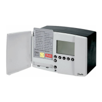
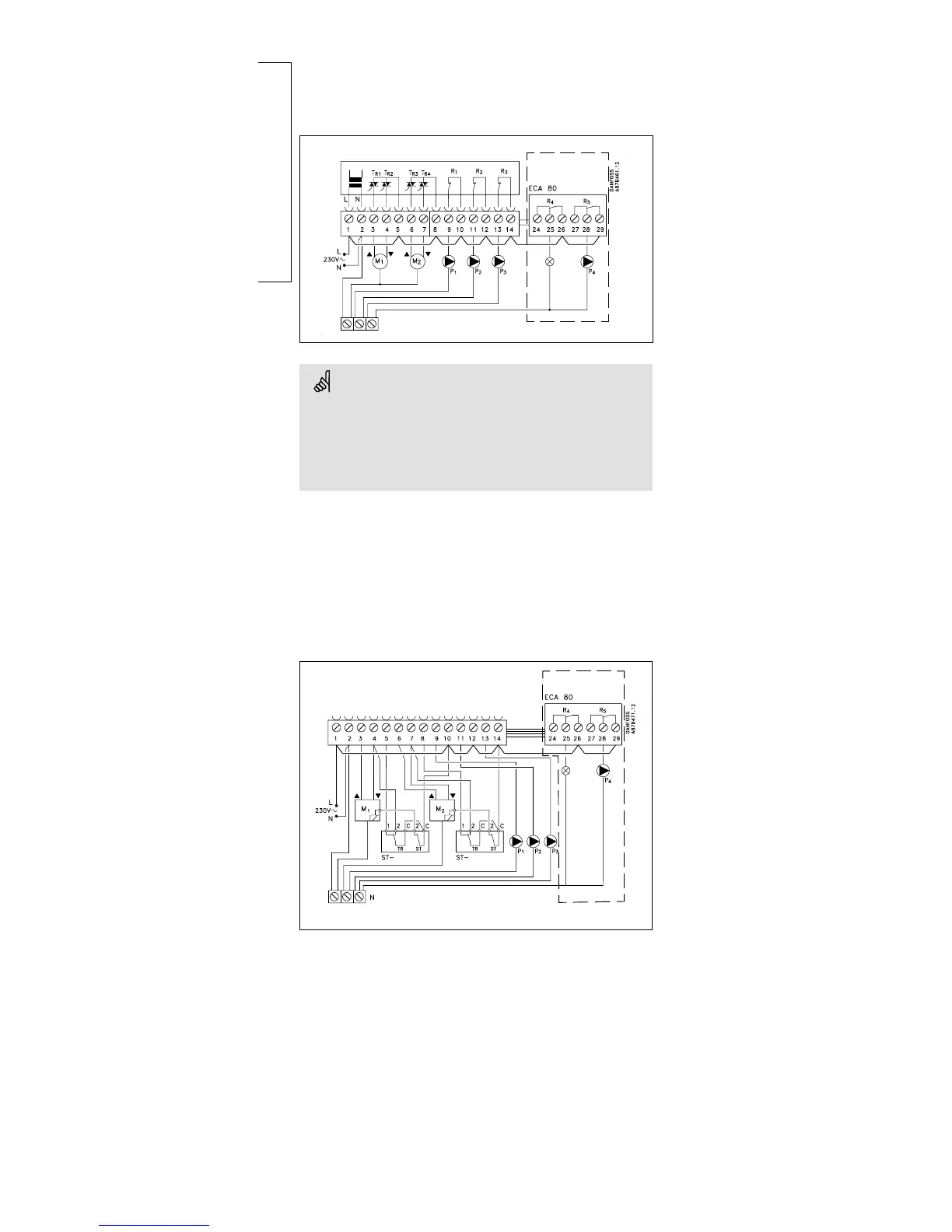
Guide to identifying different system types compatible with the ECL Comfort controller.

Mounting the ECL Comfort controller

Mounting on a wall

Details for mounting the controller onto a wall surface.

Mounting on a DIN rail

Steps for mounting the controller onto a DIN rail.

Connecting and placing the temperature sensors

Inserting the ECL Card

Basic Set-up

Basic set-up

Control parameters - lines 4-7

Configuring proportional band, integration time, and valve running time.

Control & overviews

Service parameters (10-199)

Detailed service parameters for heating circuit I.

Extended Service