Installation
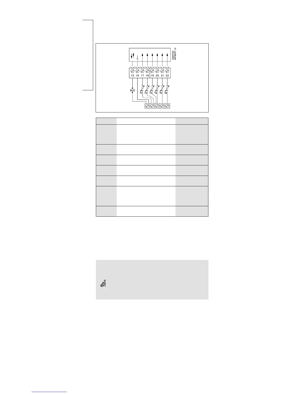
Connecting the temperature sensors and the bus
Terminal Description Type (recomm.)
15 and 16 System device bus*,
connections for room
panel** / remote control** /
(relay module)
ECA 60 / 62
ECA 61 / 63
17 and 16 S1 Outdoor temperature
sensor
ESMT
18 and 16 S2 Flow temperature sensor **,
circuit I
ESM-11 / ESMC /
ESMU
19 and 16 S3 Return temperature sensor,
circuit I
ESM-11 / ESMC /
ESMU
20 and 16 S4 Flow temperature sensor,
circuit II
ESM-11 / ESMC /
ESMU
21 and 16 S5 Return temperature sensor,
circuit II or
lower DHW tank
temperature sensor, circuit II
ESM-11 / ESMC /
ESMU
ESMB
22 and 16 S6 Upper DHW tank
temperature sensor***
ESMB / ESMU
* The system device bus / room panel / remote control is only active
when the outdoor temperature sensor is connected.
** Either room temperature sensor or room panel / remote control
*** If only one DHW tank temperature sensor is used, it must be connected
to terminal 22
Establish the jumper from 16 to common terminal.
Wire cross section for sensor connections:
Min. 0.4 mm
2
Total cable length: Max. 125 m (all sensors incl. system device
bus)
Cable lengths of more than 125 m may cause noise sensibility
(EMC).
Connecting and placing the
temperature sensors
14a
 Loading...