Installation
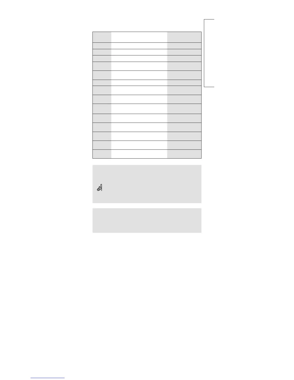
Terminal Description Max. load
1 (L) Supply voltage 24 V a.c.
2 (N) Supply voltage 24 V a.c.
3 M1 Actuator - open, circuit I 1.0 A / 24 V a.c.
4 M1
Actuator - close, circuit I
alt. thermo actuator
1.0 A / 24 V a.c.
5
24 V a.c. supply for motor
output, circuit I
6 M2 Actuator - open, circuit II 1.0 A / 24 V a.c.
7 M2
Actuator - close, circuit II
alt. thermo actuator
1.0 A / 24 V a.c.
8
24 V a.c. supply for motor
output, circuit II
9 P1
Circulation pump for heating
circuit I
4 (2) A / 24 V a.c.
10
24 V a.c. supply for pump
relay R1
11 P2
DHW charging pump for DHW
circuit II
4 (2) A / 24 V a.c.
12
24 V a.c. supply for pump
relay R2
13 P3
Circulation pump for DHW
circuit II
4 (2) A / 24 V a.c.
14
24 V a.c. supply for pump
relay R3
Wire cross section: 0.75 - 1.5 mm
2
Electrical connections
Max. 2 x 1.5 mm
2
wires can be inserted into each screw terminal.
Incorrect connection can damage the TRIAC outputs. Max. load
(terminals 3, 4, (6 and 7)) 1 A / 24 V a.c.!
Option:
Relay module ECA 80 (contacts: max. load 4 (2) A / 230 V a.c.)
25 (R4) Alarm relay output
28 (R5) Control of the DHW charging pump in heating
systems 4, 5, 6 and 6a.
13b
 Loading...