FC 300 Design Guide
How to Install
NOTE
Voltages up to 975 V DC (@ 600 V AC) may occur between the terminals.
NOTE
If a short circuit in the brake resistor occurs, prevent powe r dissipation in the brake resistor
by using a mains switch or contactor to disconnect the ma ins for the adjustable frequency
drive. Only the adjustable frequency drive can control the contactor.
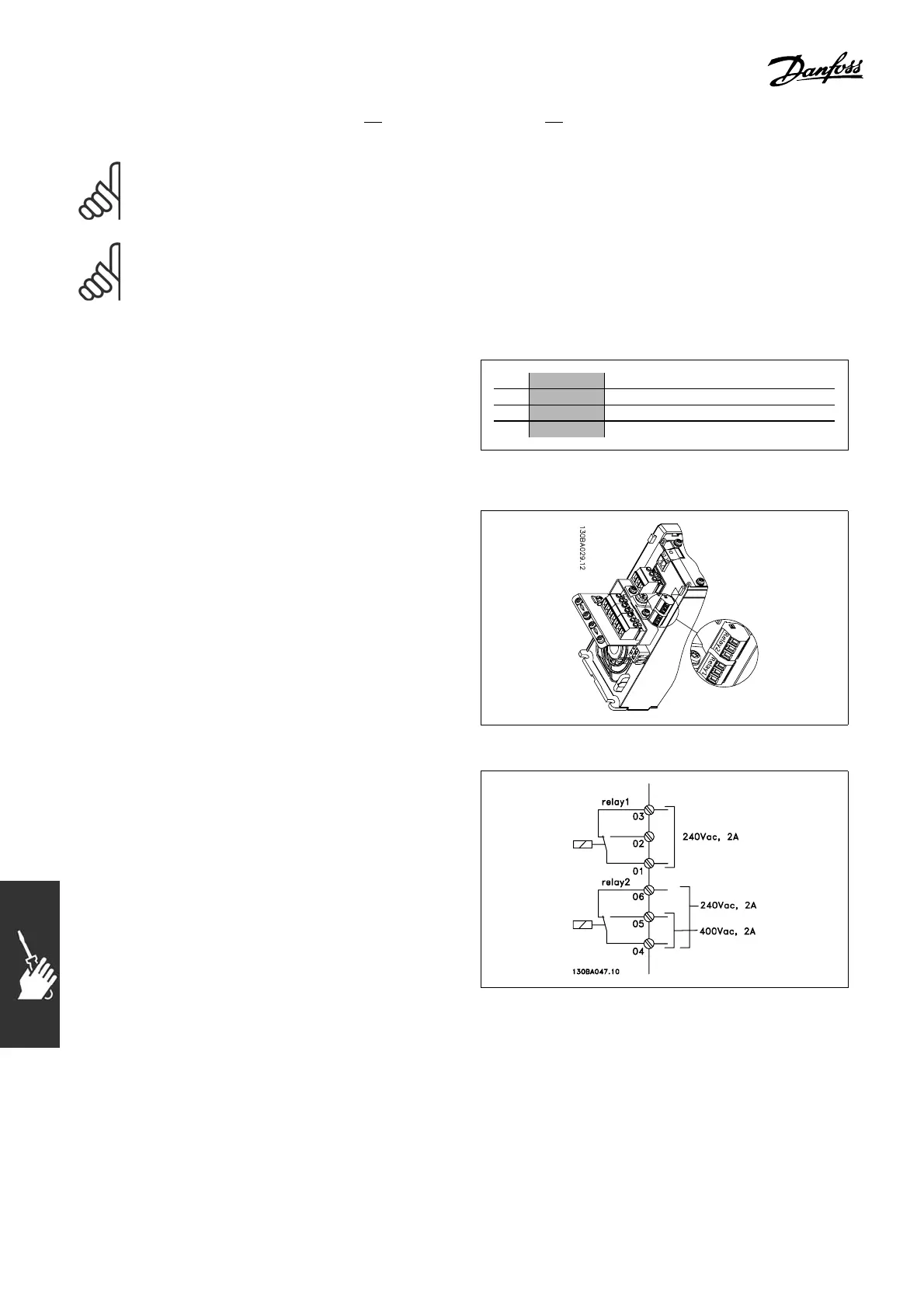
" Relay connection
To set relay output, see parameter group
5-4* Relays.
No. 01 - 02 make (normally open)
01 - 03 break (normally closed)
04 - 05 make (normally open)
04 - 06 break (normally closed)
Terminals for relay connection.
"
Relay Output
Relay 1
• Terminal 01: common
• Term inal 02: normal open 240 V AC
• Term inal 03: normal closed 240 V AC
Relay 2
• Terminal 04: common
• Term inal 05: normal open 400 V AC
• Term inal 06: normal closed 240 V AC
Relay 1 and relay 2 are programmed in par.
5-40, 5-41, and 5-42.
Additional relay outputs by using option
module MCB 105.
102
MG.33.B3.22 - VLT is a registered Danfoss trademark
 Loading...


