FC 300 Design Guide
Introduction to FC 300
Analog 53
S201=OFF
Analog 53
S201=ON
Analog 54
S202=OFF
Analog 54
S202=ON
Pulse Input
29
Pulse Input
33
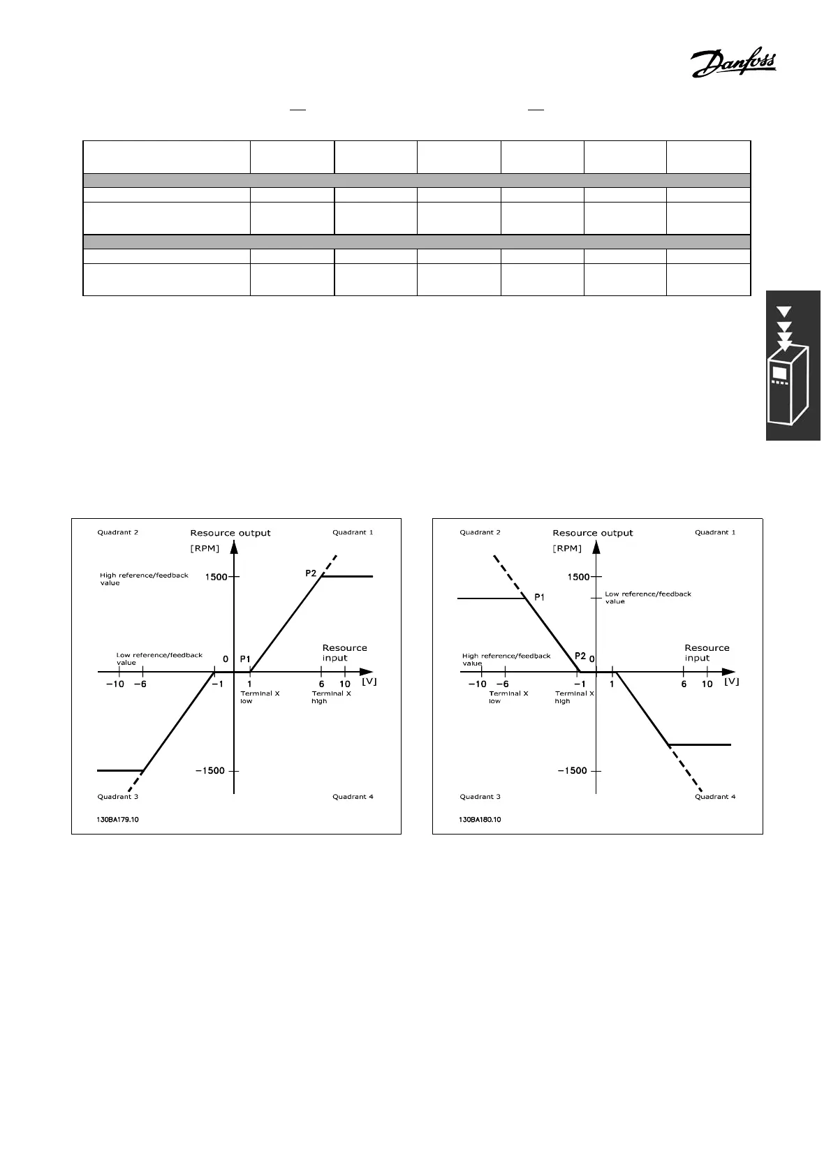
P1 = (Minimum input value, Minimum reference value)
Minimum referenc e value Par. 6-14 Par. 6-14 Par. 6-24 Par. 6-24 Par. 5-52 Par. 5-57
Minimum inpu t value Par. 6-10
[V]
Par. 6-12
[mA]
Par. 6-20
[V]
Par. 6-22
[mA]
Par. 5-50
[Hz]
Par. 5-55
[Hz]
P2 = (Maximu m input value, Maximum refe r en ce value)
Maximum reference value Par. 6-15 Par. 6-15 Par. 6-25 Par. 6-25 Par. 5-53 Par. 5-58
Maximum input value Par. 6-11
[V]
Par. 6-13
[mA]
Par. 6-21
[V]
Par. 6-23
[mA]
Par. 5-51
[Hz]
Par. 5-56
[Hz]
In s ome cases, the reference (in rare cases also the f ee dback) should have a Dead Band around zero
(i.e. to make sure the machine is stopped when the reference is "near zero"). To make the dead band
active and to set the amount of dead band, the
following settings must be done:
• Either M inimu m Reference Value (see table above for relevant parameter) or Maximum Reference Value
must be zero. In o ther words; Either P1 or P2 must be on the X-axis in t he graph be low.
• And both points defining the scaling
graph are in the same quadrant.
The size of the Dead Band is defined b
y either P1 or P2 as shown in the graph below.
Thus a reference endpoint of P1 = (0 V, 0 RPM) will not result in any dead band.
27
MG.33.B3.22 - VLT is a registered Danfoss trademark
 Loading...


