FC 300 Design Guide
How to Read this Design Guide
Set-up:
You can save parameter settings in four set-ups. Change betw ee n the four parameter set-ups
and edit one set-up, while another set-up is active.
S
FAVM
Switching pattern called S tator F lux oriented A synchronous V ector M odulation (pa r. 14-00).
S
lip Compensation:
The adjustable frequency drive compensates for the motor slip by giving the frequency a
supplement that follow s the measured motor load.
T
hermistor:
A temperature-dependent resistor placed where the temperature is to be monitored
(adjustable frequency drive or motor).
T
rip:
A state which occurs in different situations, i.e. DC link voltage is too high or too low, m o tor tem perature is too
high, etc. A trip can be cancele d by pressing reset or, in some case s, be programmed to
reset automatically.
T
rip Locked:
A state which occurs in different situations, i.e. short circuit of motor terminals, ground fault, etc. A
locked trip can b e canceled by cutting off mains and restarting the adjustable frequency drive.
V
T Characteris tics:
Variable Torque characteristics used for pumps and fans.
V
VC
plus
If compared with standard voltage/frequency ratio control, Voltage Vector Control (VVC
plus
)improvesthe
dynamics a n d the stability, both when the speed reference is changed and in relation to the loa d torque.
6
0° AVM
Switching patt ern called 60° A synchronous V ector M odulation (
par. 14-00).
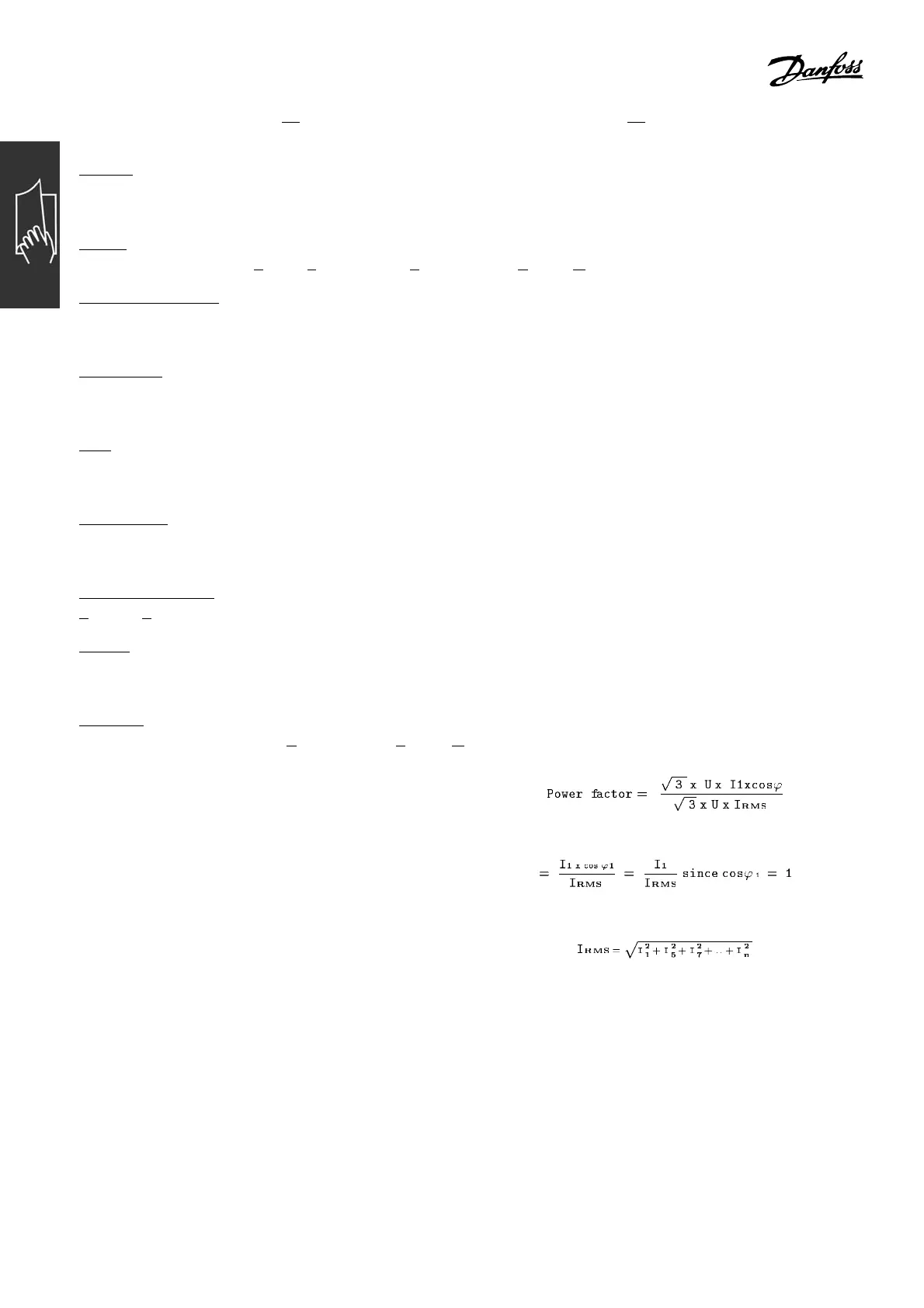
" Power Factor
The power factor is the relation between I
1
and I
RMS
.
The power factor for 3-phase control:
The power factor indicates to what extent
theadjustablefrequencydriveimposesa
load on the mains supply.
The lower the power factor, the higher the I
RMS
for the same HP/kW performance.
In addition, a high power factor indicates that the different harmonic currents are low.
The FC 300 adjustable frequency d rives’ built-in DC coils produce a high pow er factor,
which minim izes the imposed load on the mains supply.
12
MG.33.B3.22 - VLT is a registered Danfoss trademark
 Loading...


