FC 300 Design Guide
How to Install
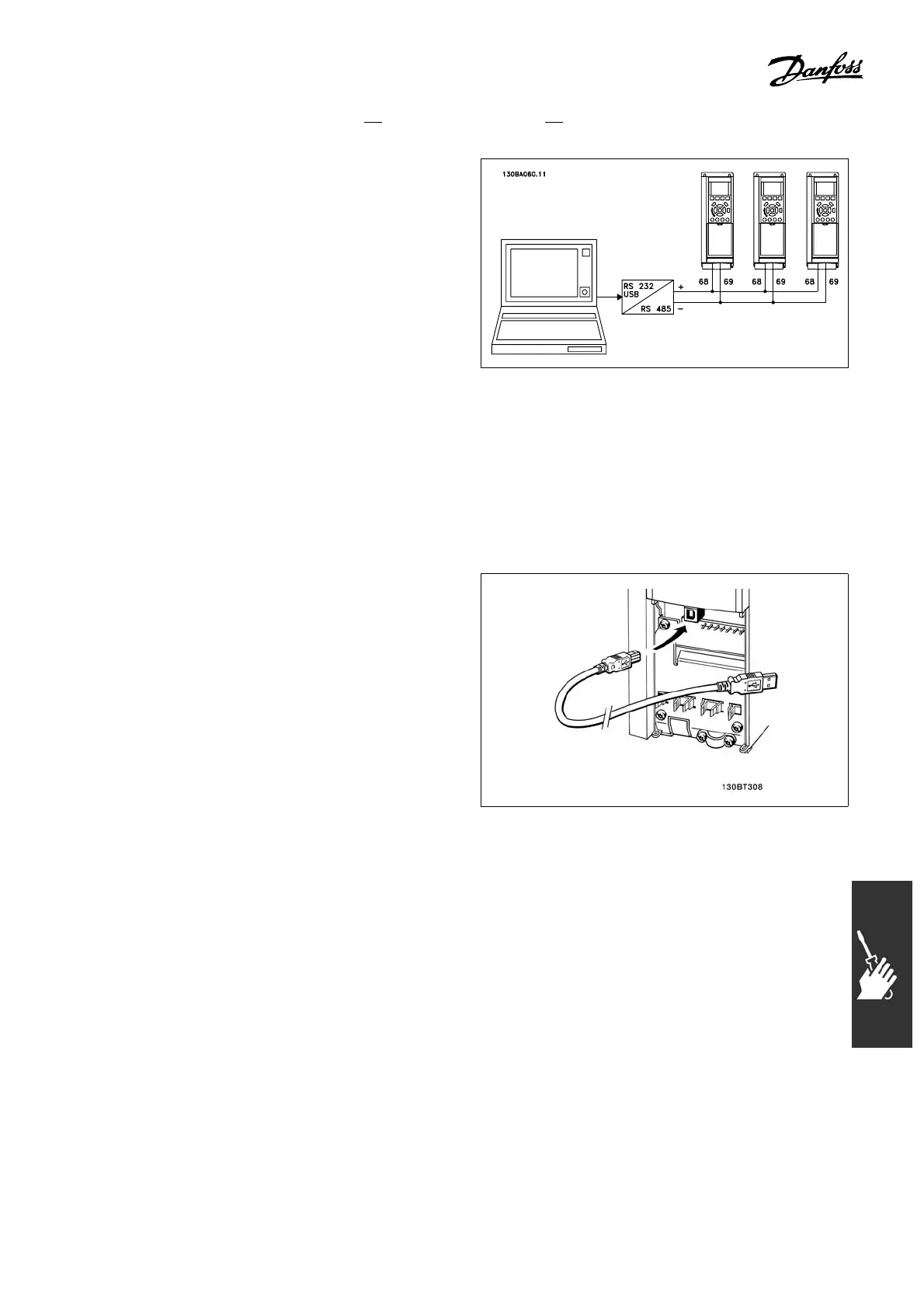
" Bus Connection
One or more adjustable frequency drives can
be connected to a controller (or master) using
the RS-485 standardized interface. Terminal 68
is connected to the P signal (TX+, RX+), while
terminal 69 is connected to the N signal (TX-,RX-).
Ifmorethanoneadjustablefrequencydriveis
connected to a master, use p arallel connections.
In order to avoid potential equalizing currents in the shield, ground the cable shield via
terminal 61, which is connecte d to the frame via an RC-link.
Bus termination
TheRS-485busmustbeterminatedbyaresistor network at both ends. For this purpose,
set switch S801 on the control card to "ON".
For more information, see the paragraph SwitchesS201,S202,andS801.
" HowtoConnectaPCtotheFC300
To control the adjustable frequency drive from a
PC, install the MCT 10 Setup Software.
The PC is connec ted via a standard (host/device)
USB cable, or via the R S -485 interface as
showninthesectionBus Connection in the
chapter How to P rogram.
USB connection.
"
The FC 300 Software Dialog
Data s
torage in PC via MCT 10 Set-U p Software:
1. Connect a PC to the unit via USB com port
2. MCT 10 Set-up Software
3. Choose
"Read from drive"
4. Choose "Save as"
All parameters are now stor ed.
Data transfer fr om PC to drive via MCT
10 Se
t-Up Softwar e:
1. Connect a PC to the unit via US B com port
2. MCT 10 Set-up Software
3. Choos
e"Open"-storedfileswillbeshown
4. Open the approp riate file
5. Choose "Write to drive"
All par
ameters are now transferred to the drive.
Asepa
rate ma nual for MCT 10 Set-up
Software is available.
105
MG.33.B3.22 - VLT is a registered Danfoss trademark
 Loading...


