FC 300 Design Guide
How to Install
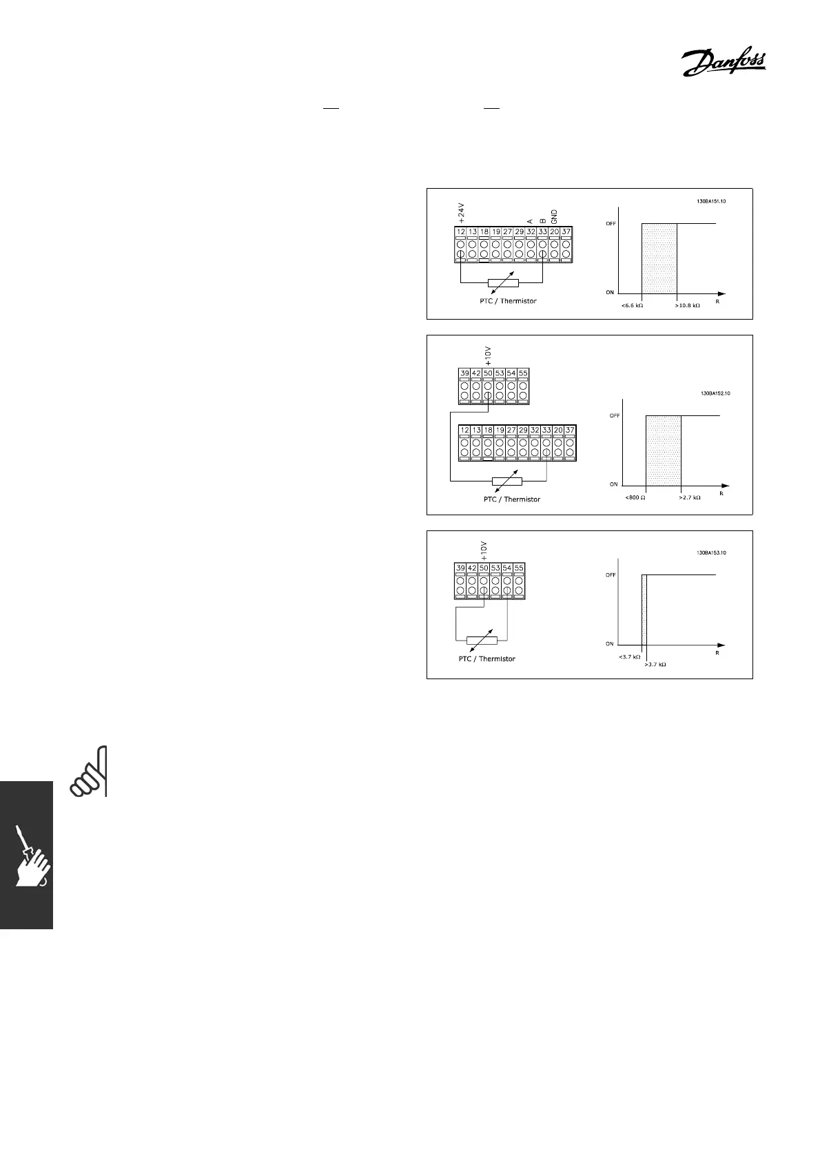
" Thermal Motor Protection
Connection of thermal motor protection device (PTC or ’Klixon’ NC switch):
Using a digital input and 24 V as power supply:
Example: Adjustable frequency drive trips when
motor temperature too h ig h
Parameter set-up:
Par. 1-90 Thermistor trip [2]
Par. 1-93 Digital Input [6]
Using a digital input and 10 V as power supply:
Example: Adjustable frequency drive trips when
motor temperature too h ig h
Parameter set-up:
Par. 1-90 Thermistor trip [2]
Par. 1-93 Digital Input [6]
Using an analog input and 10 V as power supply:
Example: Adjustable frequency drive trips when
motor temperature too h ig h
Parameter set-up:
Par. 1-90 Thermistor trip [2]
Par. 1-93 Analog Input 54 [2]
(No reference source must be selected)
" Electrical Installation of Motor Cables
NOTE
If an non-shielded cable is used, some EMC requirements are not complied with.
The m otor cab le must be shielded in order to comply with the EMC specifications regarding
emission, unless otherwise stated for the RFI filter. Keep the motor cable as short as
possible to reduce the noise level and leakage currents t o a minimum.
Connect the m otor cable shield to the metal cabinet of the adjustable frequency drive and to the metal
cabinet of the motor. Make the shield connections with the largest p ossib le surface (cable clamp). This is
done by using different installation devices in the various adjustable frequency drives.
Shielding of cables
Avoid installation with twisted shield ends (pigtails). They spoil the shielding effect at higher frequencies.
90
MG.33.B3.22 - VLT is a registered Danfoss trademark
 Loading...


