FC 300 Design Guide
Introduction to FC 300
" Speed PID Control
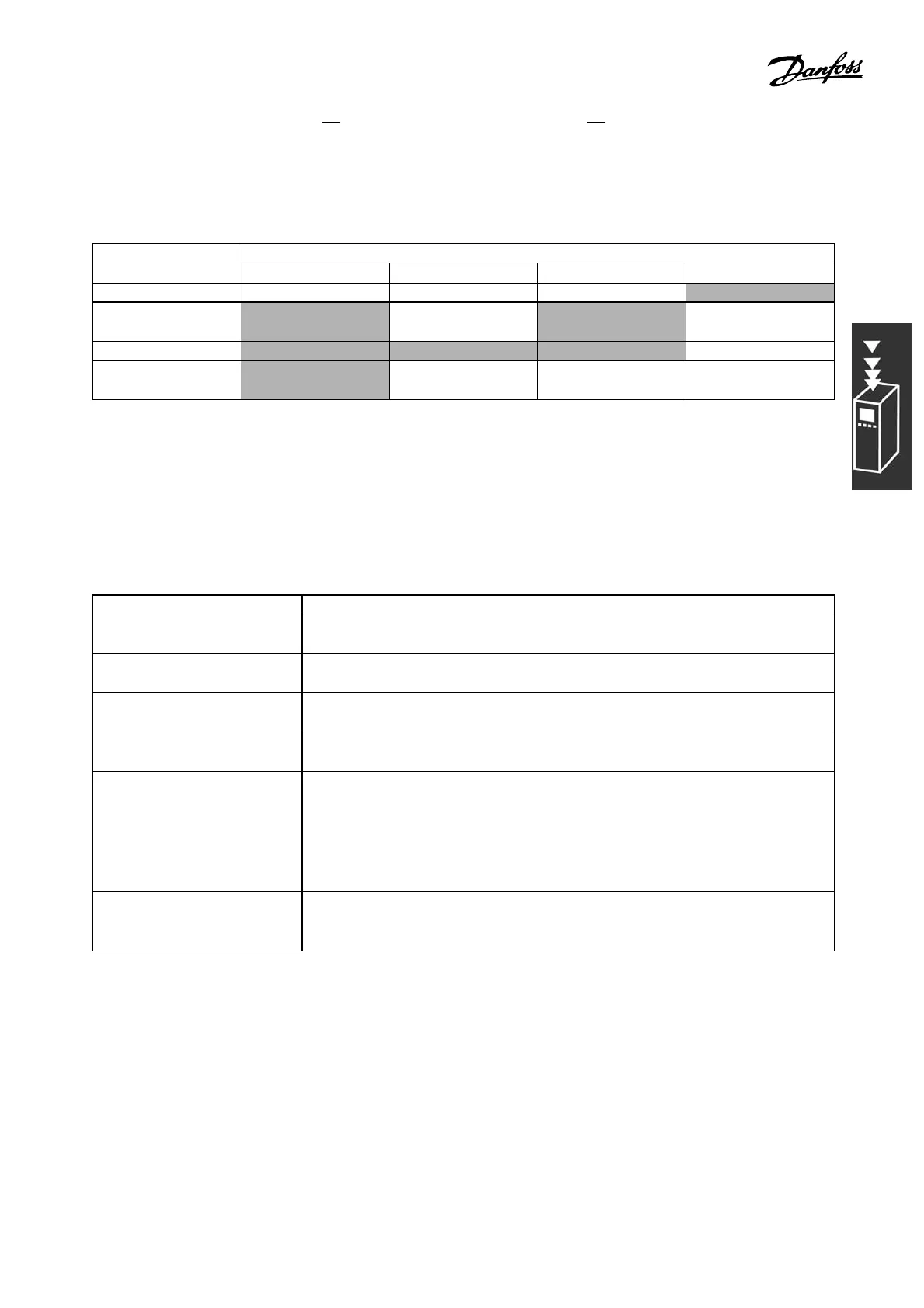
The table shows the control configurations w here the Speed Control is active. To see where the
Speed Control is active, please refer to the section about the Control Structure.
Par. 1-01 Motor Control PrinciplePar. 1-00
Configuration Mode
U/f VVCplus Flux sensorless Flux w motor feedb
[0] Speed open loop Not Active Not Active ACTIVE N.A.
[1] Speed
closed-loop
N.A. ACTIVE N.A. ACTIVE
[2] Torque N.A. N.A. N.A. Not Active
[3] Pro cess
open-loop
N.A. Not Active ACTIVE ACTIVE
Note: "N.A." means that the specific mode is not available at all. "Not Active" means that the
specific mode is available but the Speed Control is not active in that mode.
Note: The Speed Control PID will work under the default pa rameter setting, but tuning the p arameters
is highly recom m ended to optimize the motor control performance. The two Flux m oto r control
principles are specially dependent on proper tuning to yield their full potential.
The following parameters a re re levant for the Speed Control:
Parameter Description of function
Speed PID Feedback Resource
Par. 7-00
Select from which resource (i.e. analog or pulse input) the Speed PID should get
its feedback
Speed PID Proportional G ain
Par. 7-02
The higher the value, the quicker the c ontrol. However, too high a value may
lead to oscillations.
Speed PID Integral Time
Par.
7-03
Eliminates steady stat
e speed error. Lower value m eans quick reaction. However,
toolowavaluemayleadtooscillations.
Speed PID Differentiation Tim e
Par. 7-04
Provides a gain proportional to t he rate of change of the feedback. A setting of
zero disables the differentiator.
Speed PID Diff. Gain Limit Par.
7-05
If there are quick changes in reference or feedback in a given application - which
means that the error
changes swiftly - the differentiator may soon become too
dominant. This is because it reacts to changes in the error. The quicker the error
changes, the stronger the differentiator gain is. The differentiator gain can thus be
limited to allo
w setting of the reasonable differentiation time for slow changes and
a suitably quick g a in for quick changes .
Speed PID Lowpass Filter Time
Par. 7-06
A low-pass filter that dampen s oscillations on the feedback signal and improves
steady state performance. Howeve r, too large a filter time w ill deteriorate the
dynamic perfo
rmance of the Speed PID control.
33
MG.33.B3.22 - VLT is a registered Danfoss trademark
 Loading...


