FC 300 Design Guide
How to Install
" Tightening torques
Tighten power, electrical, brake, and gro und
terminals with the following torques:
FC 300 Connections Torqu e ( N m )
Motor, electrical supply,
brake, DC Bus
2-3
1.5-2.2 lb-ft
Ground, 24 DC 2-3
Relay, DC filter feedback 0.5-0.6
0.35-0.45
lb-ft
" Final Set-Up and Test
To test the set-up and ensure that the adjustable frequency drive is running, follow these steps.
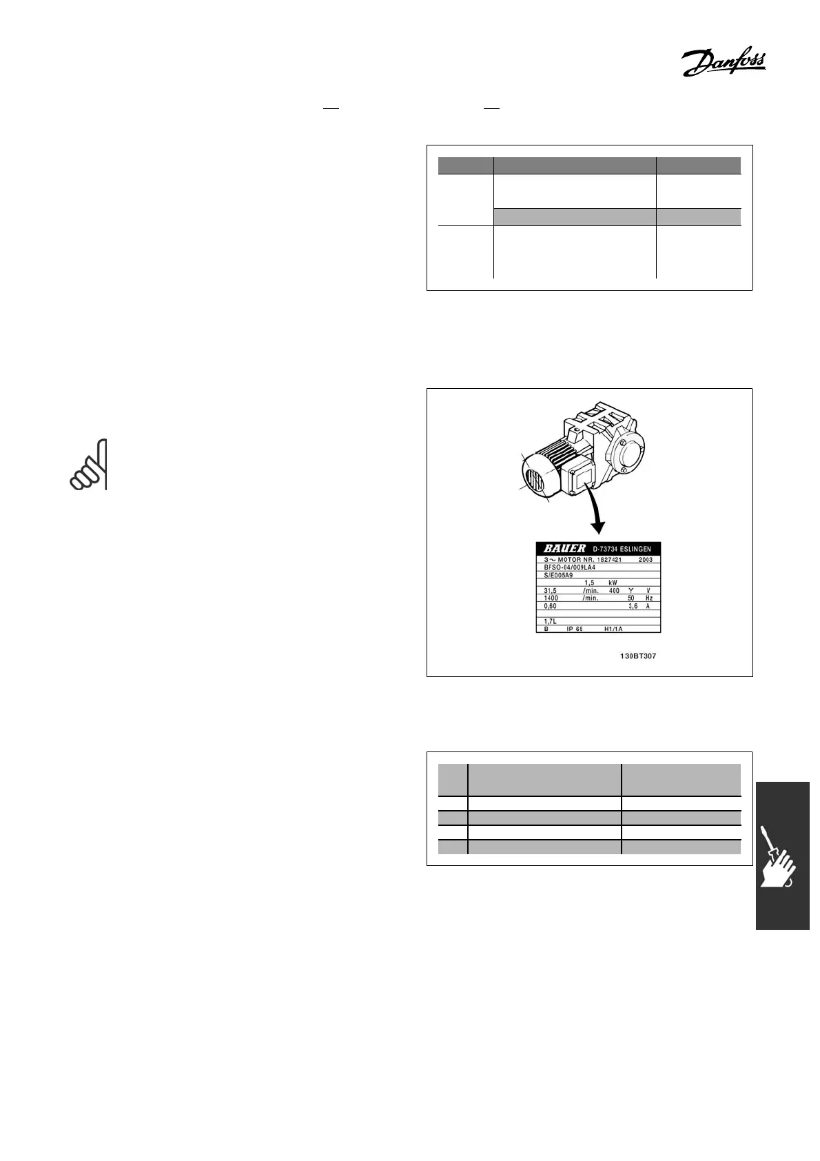
Step 1. Locate the motor nameplate.
NOTE
The motor is either star- (Y) or delta-
connected (∆). This information is located
on the motor nameplate data.
Step2. Enterthemotornamep
late data
in this parameter list.
To access this list, first p ress the [QUICK MENU]
key then select “Q2 Quick Se
tup”.
1. Motor Power [kW]
or Motor Power [HP]
par. 1-20
par. 1-21
2. Motor Voltage par. 1-22
3. Motor Frequency par. 1-23
4. Motor Current par. 1-24
5. Motor Nominal Speed par. 1-25
Step 3. Activate the Automatic Motor Adapta tion (AM A)
Performing an AMA will ensure optimum performance. The AMA measures the values
from the motor model equivalent diagram.
97
MG.33.B3.22 - VLT is a registered Danfoss trademark
 Loading...


