FC 300 Design Guide
How to Install
" ControlofMechanicalBrake
Control an ele ctromechanical brake in hoisting/lowe ring applications.
• Control the brake using any relay output or digital output (terminal 27 or 29).
• Keep the outp ut closed (voltage-free) as long as the adjustable frequency drive is unable to
"support" the motor, for example due to the load being too heavy.
• Select Mechanical brake control [32] in par. 5-4* for applications with an electromechanical brake.
• The brake is released when the motor current exceeds the preset value in par. 2-20.
• The brake is engaged when the output frequency is less than the frequency set in par. 2-21 or
2-22, and only if the adjustable frequency drive carries out a stop command.
If the adjustable f requency drive is in alarm mode or in an overvoltage situation, the
mechanical brake immediately cuts in.
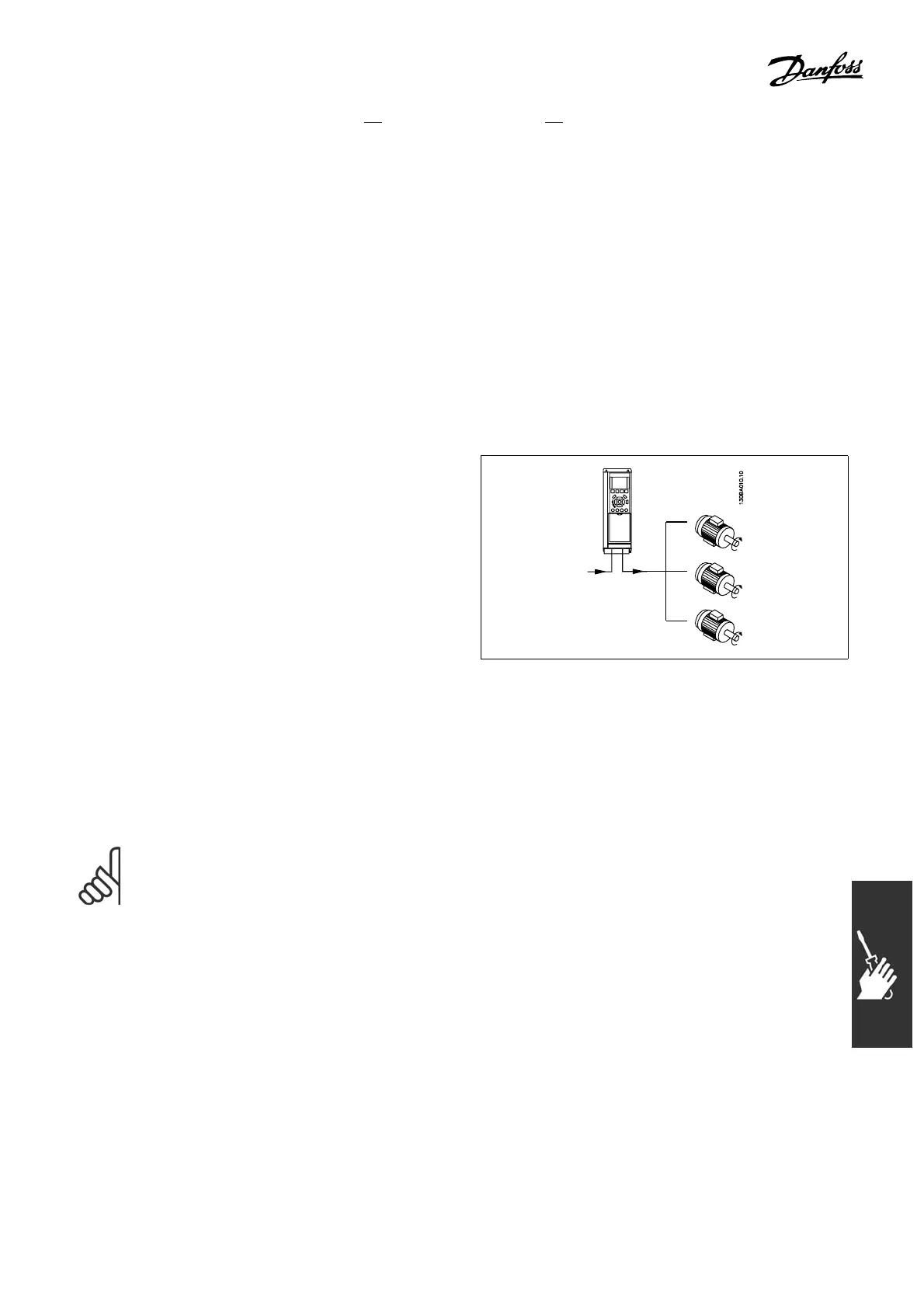
" Parallel Connection of Motors
The adjustable frequency drive can control
several motors connected in parallel. The total
current consumption of the motors must not
exceed the rated output current I
INV
for the
adjustable frequency drive.
This is only recom mended when VVC
plus
is
selected in par. 1-01.
Problems may arise at start and at low RPM values if motor sizes are wid ely different because small motors’
relatively high ohmic resista nce in the stator requires a h igher voltage at start and to operate at low RPM values.
Theelectronicthermalrelay(ETR)oftheadjustablefrequencydrivecannotbeusedasmotorprotectionfor
the individual motor of syst em s with parallel-connected motors. Provide further motor protection by e.g.
thermistors in each motor or individual thermal relays. (Circuit b reakers are not suitable as protection).
NOTE
When motors are connected in parallel, par. 1-02 Automat ic motor ad aptation (AMA) cannot be
used, and par. 1-01 Torque characteristics must be set to Special motor characteristics.
103
MG.33.B3.22 - VLT is a registered Danfoss trademark
 Loading...


