FC 300 Design Guide
Introduction to FC 300
Intheparameterlistbelow,itisassumedthatallotherparameters and switches remain at their default setting.
The following must be programmed in the order s hown - see explanation of set-
tings in the section "How to Program."
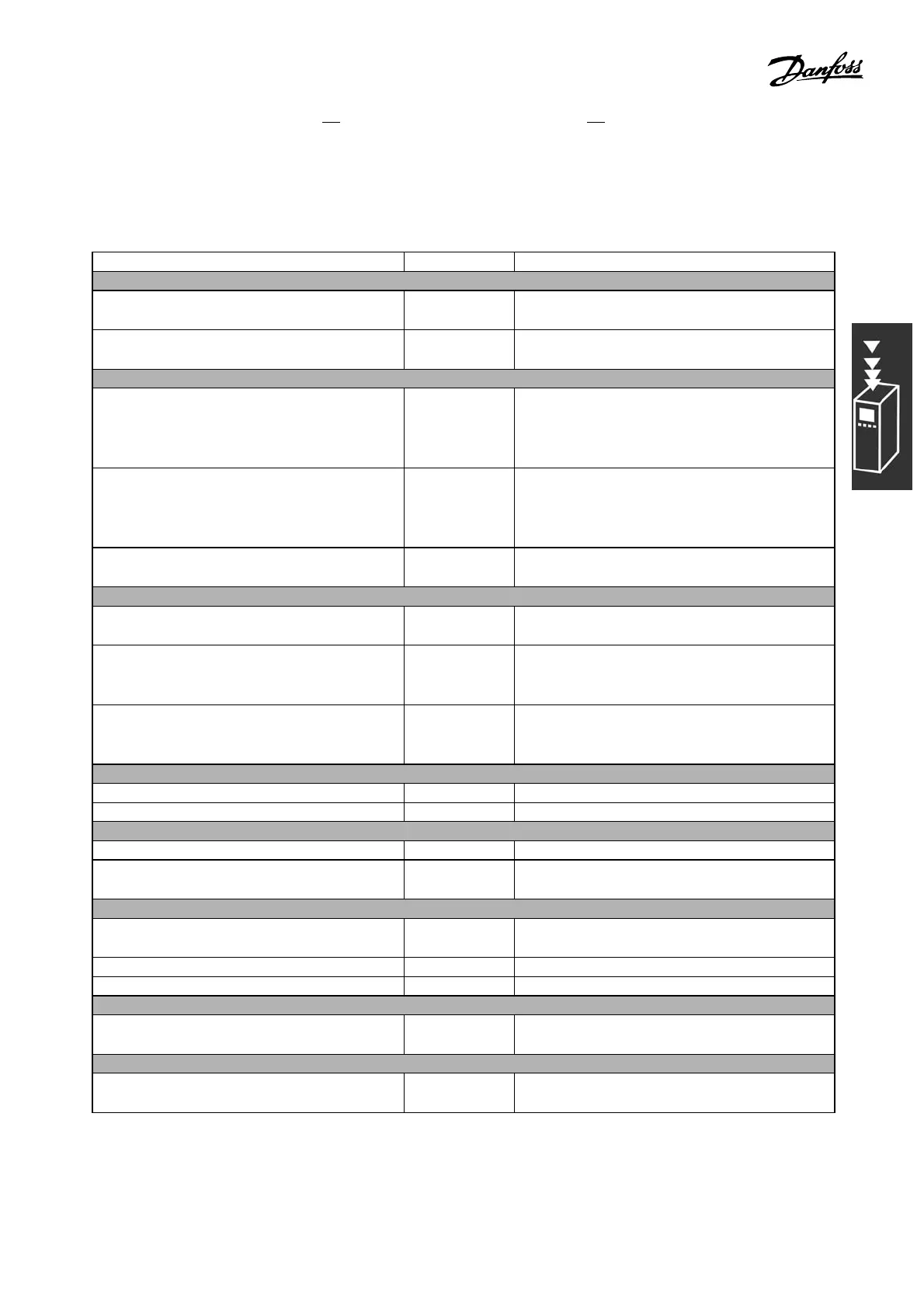
Function Par. no. Setting
1) Make sure the motor runs prop erly. Do the following:
Set the motor parameters using nameplate
data
1-2* As specified by m otor nameplate
Have the VLT make an Automatic Motor
Adaptation
1-29 [1]EnablecompleteAMA
2) Check that the motor is running and the encoder is attached properly. Do the following:
Press the "Hand On" LCP key. Check that the
motor is running and note in which direction
it is turning (henceforth re ferred to as the
"positive direction").
Set a positive reference.
Go to par. 16-20. Turn the motor slowly in the
positive direction. It must be turn ed so slowly
(onlyafewRPM)thatitcanbedeterminedifthe
value in par. 16-20 is increasing or decreasing.
16-20 N.A. (read-only parameter) Note: An increasing
value overflows at 65535 and starts again at 0.
If par. 16-20 is decreasing, then ch ange the
encoder direction in par. 5-71.
5-71 [1] Counter clockwise (if par. 16-20 is
decreasing)
3) Make sure the drive limits are set to safe values
Set acceptable limits for the referenc es . 3-02
3-03
0RPM(default)
1500 RPM (default)
Check that the ramp settings are within drive
capabilities and allowed application operating
specifications.
3-41
3-42
3sec. (default)
3sec. (default)
Set acceptable limits for the motor speed and
frequency.
4-11
4-13
4-19
0RPM(default)
1500 RPM (default)
60 Hz (default 132 Hz)
4) Configure the Speed Control and select the Motor Control principle
Activation of S peed Control 1-00 [1] Speed closed-loop
Selection of Motor Control Principle 1-01 [3] F lux w motor feedb
5) Configure and scale the reference to the Speed Control
Set up Analog Input 53 as a reference resource 3-15 Not necessary (default)
Scale Analog Input 53 0 RPM (0 V) to 1500
RPM (10V)
6-1* Not neces sary (default)
6) Configure the 24V HTL encoder s ignal as feedback for the Motor Control and the Speed Control
Set up digital input 3 2 and 33 as encoder inputs 5-14
5-15
[0] No operation (defau lt)
Choose terminal 32/33 as motor feedback 1-02 Not neces sary (default)
Choose terminal 32/33 as Speed PID feedback 7-00 Not nec es sary (default)
7) Tun e the Speed Control PID parameters
Use t he tuning guidelines when relevant or
tune manually
7-0* See the guidelines below
8) Finished!
Save the parameter settings to the LCP for
safekeeping
0-50 [1] All to LCP
35
MG.33.B3.22 - VLT is a registered Danfoss trademark
 Loading...


