EasyManuals Logo
Home>Danfoss>DC Drives>VLT AutomationDrive FC 300

Danfoss VLT AutomationDrive FC 300 Design Guide

Danfoss VLT AutomationDrive FC 300
296 pages
To Next Page IconTo Next Page
To Previous Page IconTo Previous Page
Page #171 background imageLoading...
Page #171 background image
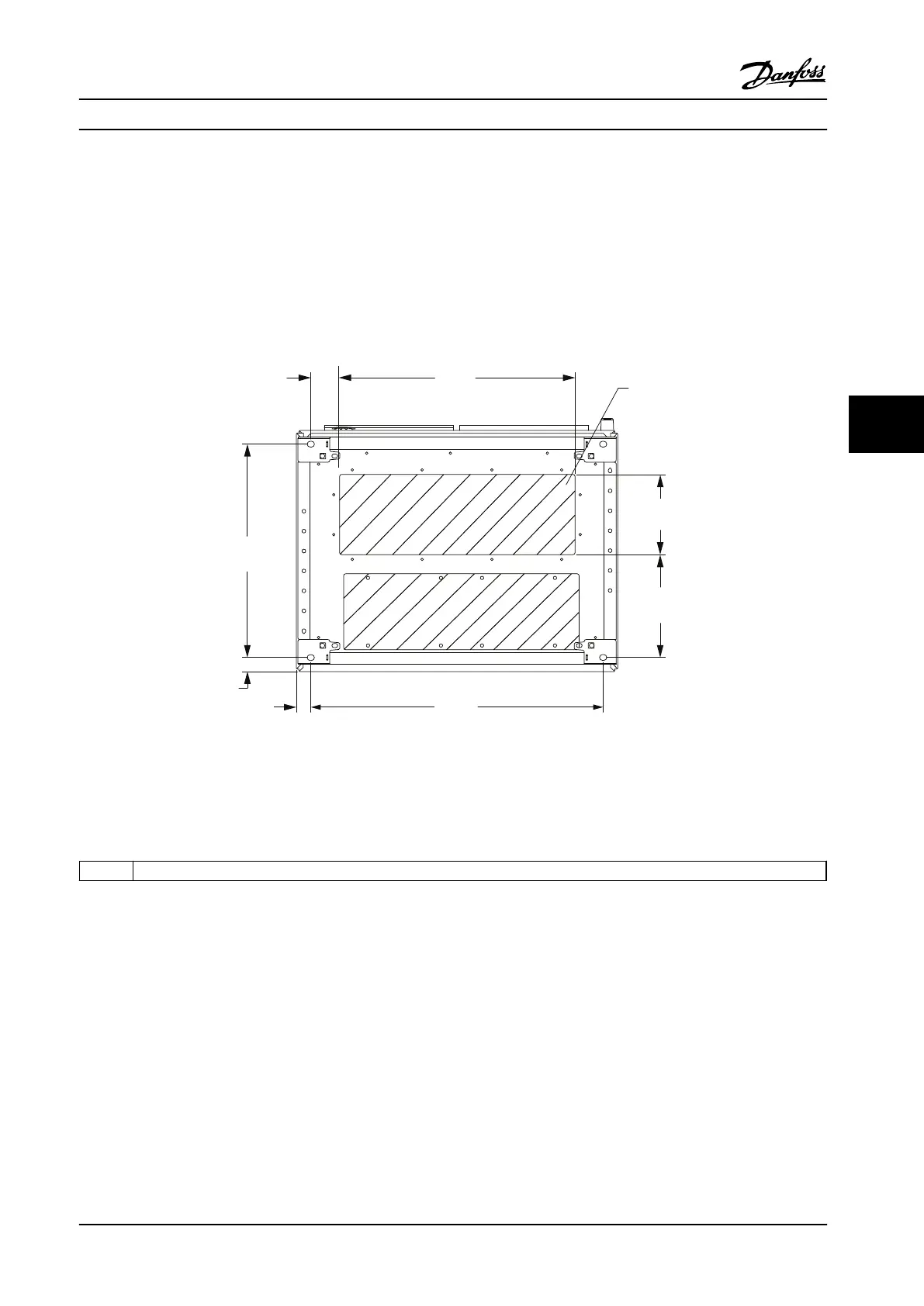
6.2.8 Connector/Conduit Entry, 12-Pulse - IP21 (NEMA 1) and IP54 (NEMA12)
The following figures show the cable entry points as viewed from the bottom of the adjustable frequency drive.
733.0
[ 28.858 ]
258.5
[10.177 ]
199.5
[ 7.854 ]
1
593.0
[ 23.326 ]
70.0
[ 2.756 ]
535.0
21.063 ]
35.5
[ 1 ]
36.5
[ 1.437 ]
130BB533.11
Figure 6.89 Frame Size F8
1
Place conduits in shaded areas
Table 6.56 Legend to Figure 6.89
Mechanical Installation Design Guide
MG34S222 Danfoss A/S © Rev. 2014-02-10 All rights reserved. 169
6 6

Table of Contents

Other manuals for Danfoss VLT AutomationDrive FC 300

Questions and Answers:

Question and Answer IconNeed help?

Do you have a question about the Danfoss VLT AutomationDrive FC 300 and is the answer not in the manual?

Danfoss VLT AutomationDrive FC 300 Specifications

General IconGeneral
BrandDanfoss
ModelVLT AutomationDrive FC 300
CategoryDC Drives
LanguageEnglish

Related product manuals