NOTICE!
Customer-supplied 230 V supply is required for line
power contactors.
7.4 Additional Motor Information
7.4.1 Motor Cable
All types of 3-phase asynchronous standard motors can be
used with an adjustable frequency drive unit. The motor
must be connected to the following terminals:
•
U/T1/96
•
V/T2/97
•
W/T3/98
•
ground to terminal 99
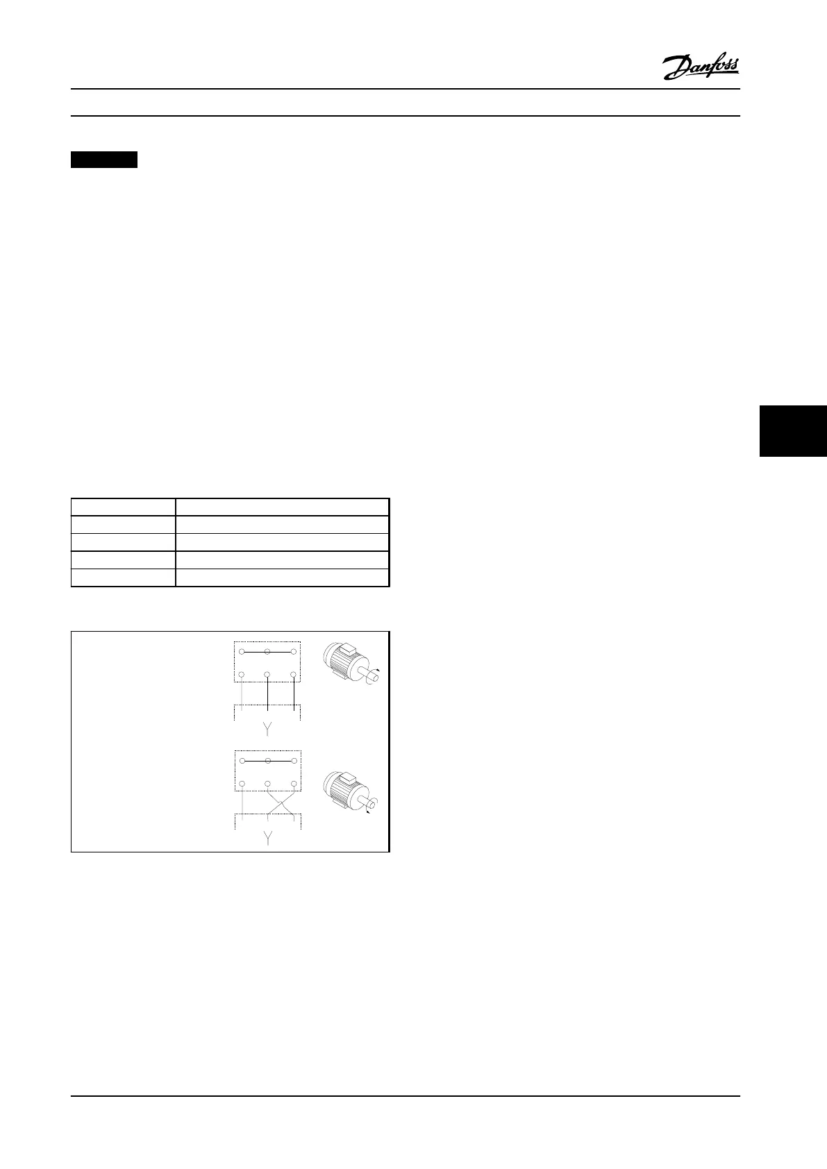
Factory setting is for clockwise rotation with the adjustable
frequency drive output connected as follows:
Terminal no. Function
96 Line power U/T1
97 V/T2
98 W/T3
99 Ground
Table 7.63 Motor Cable Terminals
•
Terminal U/T1/96 connected
to U-phase
•
Terminal V/T2/97 connected
to V-phase
•
Terminal W/T3/98
connected to W-phase
175HA036.11
U
1
V
1
W
1
96 97 98
FC
Motor
U
2
V
2
W
2
U
1
V
1
W
1
96 97 98
FC
Motor
U
2
V
2
W
2
Table 7.64 Changing Motor Rotation
The direction of rotation can be changed by switching two
phases in the motor cable, or by changing the setting of
4-10 Motor Speed Direction.
Motor rotation check can be performed using 1-28 Motor
Rotation Check and following the steps shown in
Table 7.64.
F-frame requirements
F1/F3 frame
Each inverter module must have the same number of
motor phase cables and they must be in multiples of 2 (for
example, 2, 4, 6, or 8). One cable is not allowed. The cables
are required to be equal length or within 10% between
the inverter module terminals and the first common point
of a phase. The recommended common point is the motor
terminals. For example, if inverter module A used a 100 m
cable, then subsequent inverter modules could use a cable
between 90–110 m in length.
F2/F4 frame
Each inverter module must have the same number of
motor phase cables and they must be in multiples of 3 (for
example, 3, 6, 9, or 12). One or two cables are not allowed.
The cables are required to be equal length or within 10%
between the inverter module terminals and the first
common point of a phase. The recommended common
point is the motor terminals. For example, if inverter
module A used a 100 m cable, then subsequent inverter
modules could use a cable between 90–110 m in length.
Output junction box requirements
The length (minimum 2.5 m) and quantity of cables must
be equal from each inverter module to the common
terminal in the junction box.
The electronic thermal relay in the adjustable frequency
drive has received UL-approval for single motor protection,
when 1-90 Motor Thermal Protectionis set for ETR Trip and
1-24 Motor Current is set to the rated motor current (see
the motor nameplate).
For thermal motor protection, it is also possible to use the
MCB 112 PTC thermistor card option. This card provides an
ATEX certificate to protect motors in explosion hazard
areas, Zone 1/21 and Zone 2/22. When 1-90 Motor Thermal
Protection is set to [20] ATEX ETR combined with the use of
MCB 112, it is possible to control an Ex-e motor in
explosion hazard areas. Consult the programming guide
for details on how to set up the adjustable frequency drive
for safe operation of Ex-e motors.
Electrical Installation Design Guide
MG34S222 Danfoss A/S © Rev. 2014-02-10 All rights reserved. 219
7 7
 Loading...


