7.5.7 Installing Control Cables
Electrical Installation
130BC532.10
230 VAC
50/60Hz
230 VAC
50/60Hz
TB6 Contactor
TB5
R1
Regen +
Regen -
83
Regen
1
2
Brake Temp
(NC)
Anti-condensation heater (optional)
(optional)
91 (L1)
92 (L2)
93 (L3)
PE
88 (-)
89 (+)
50 (+10 V OUT)
53 (A IN)
54 (A IN)
55 (COM A IN)
0/4-20 mA
12 (+24V OUT)
13 (+24V OUT)
18 (D IN)
20 (COM D IN)
15mA
200mA
(U) 96
(V) 97
(W) 98
(PE) 99
(COM A OUT) 39
(A OUT) 42
0/4-20 mA
03
+10Vdc
-10 VDC - +10VDC
0/4-20 mA
24Vdc
02
01
05
04
06
240Vac, 2A
24V (NPN)
0V (PNP)
0V (PNP)
24V (NPN)
19 (D IN)
24V (NPN)
0V (PNP)
27
24V
0V
(D IN/OUT)
0V (PNP)
24V (NPN)
(D IN/OUT)
0V
24V
29
24V (NPN)
0V (PNP)
0V (PNP)
24V (NPN)
33 (D IN)
32 (D IN)
1 2
ON
A53 U-I (S201)
ON
21
A54 U-I (S202)
ON=0-20mA
OFF=0-10V
95
400Vac, 2A
P 5-00
(R+) 82
(R-) 81
37 (D IN)
+ - + -
(P RS-485) 68
(N RS-485) 69
(COM RS-485) 61
0V
5V
S801
RS-485
RS-485
21
ON
S801/Bus Term.
OFF-ON
3 Phase
power
input
Load Share
Switch Mode
Power Supply
Motor
Analog Output
Interface
Relay1
Relay2
ON=Terminated
OFF=Open
Brake
resistor
(NPN) = Sink
(PNP) = Source
= ==
240Vac, 2A
400Vac, 2A
-10 VDC - +10VDC
10Vdc
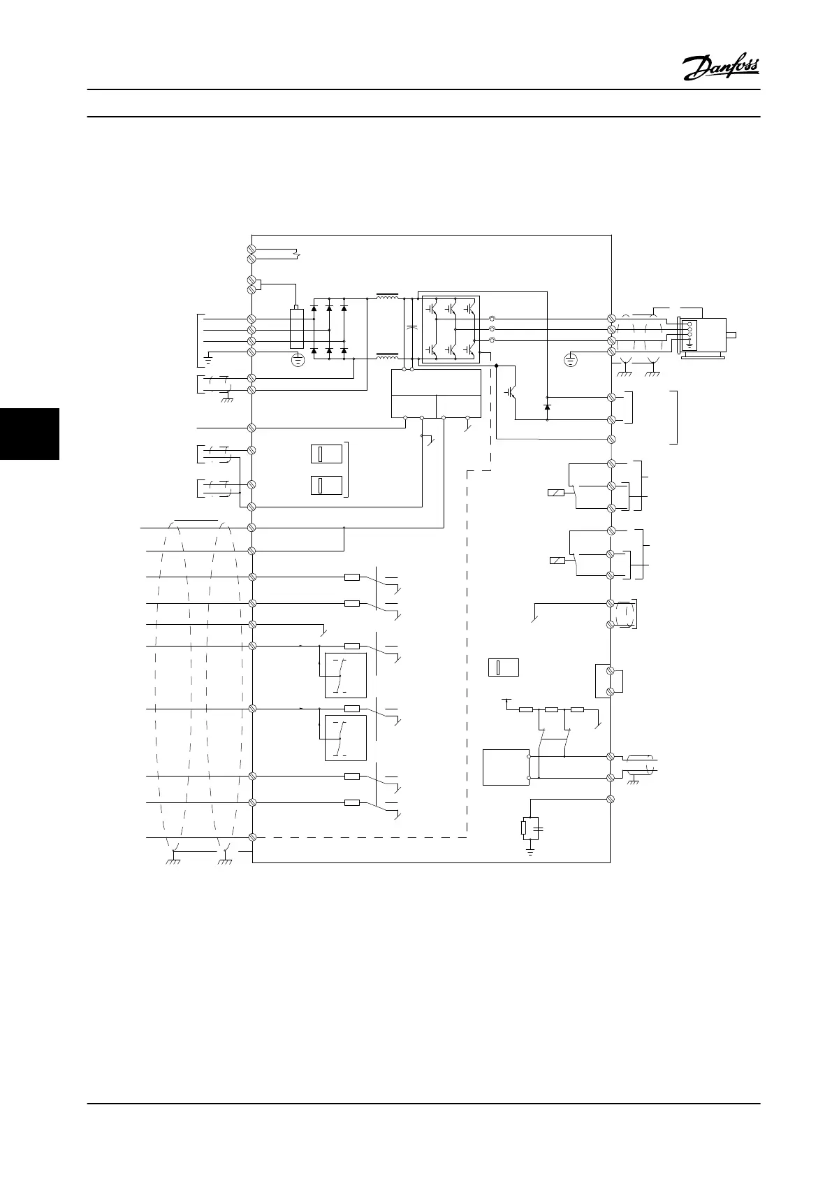
Figure 7.43 Interconnect Diagram, D-Frame Adjustable Frequency Drives (A=analog, D=digital)
Terminal 37 is used for Safe Torque Off. For Instructions on Safe Torque Off Installation, Refer to chapter 3.12 Safe Stop.
Electrical Installation Design Guide
226 Danfoss A/S © Rev. 2014-02-10 All rights reserved. MG34S222
77
 Loading...


