10.7 FC Protocol Message Framing
Structure
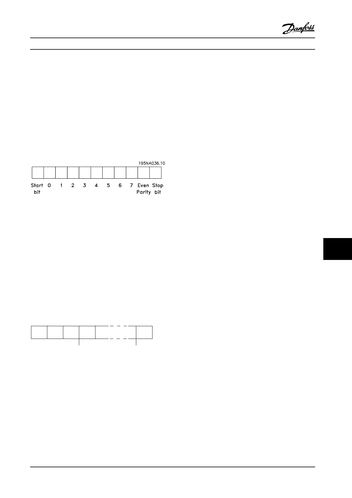
10.7.1 Content of a Character (Byte)
Each character transferred begins with a start bit. Then 8
data bits are transferred, each corresponding to a byte.
Each character is secured via a parity bit. This bit is set at
"1" when it reaches parity. Parity is when there is an equal
number of 1 characters in the 8 data bits and the parity bit
in total. A stop bit completes a character, thus consisting
of 11 bits in all.
Figure 10.4 Character (Byte)
10.7.2 Message Structure
Each message has the following structure:
1. Start character (STX)=02 Hex
2. A byte denoting the message length (LGE)
3. A byte denoting the adjustable frequency drive
address (ADR)
A number of data bytes (variable, depending on the type
of message) follows.
A data control byte (BCC) completes the message.
STX LGE ADR DATA BCC
195NA099.10
Figure 10.5 Message Structure
10.7.3 Message Length (LGE)
The message length is the number of data bytes plus the
address byte ADR and the data control byte BCC.
•
The length of messages with 4 data bytes is
LGE=4+1+1=6 bytes
•
The length of messages with 12 data bytes is
LGE=12+1+1=14 bytes
•
The length of messages containing texts is 10
1)
+n
bytes
1)
The 10 represents the fixed characters, while the “n’” is
variable (depending on the length of the text).
10.7.4
Adjustable Frequency Drive Address
(ADR)
Two different address formats are used.
The address range of the adjustable frequency drive is
either 1–31 or 1–126.
1. Address format 1–31:
Bit 7=0 (address format 1–31 active)
Bit 6 is not used
Bit 5=1: Broadcast, address bits (0–4) are not used
Bit 5=0: No Broadcast
Bit 0–4=adjustable frequency drive address 1–31
2. Address format 1–126:
Bit 7=1 (address format 1–126 active)
Bit 0–6=adjustable frequency drive address 1–126
Bit 0–6=0 Broadcast
The follower returns the address byte unchanged to the
master in the response message.
10.7.5
Data Control Byte (BCC)
The checksum is calculated as an XOR-function. Before the
first byte in the message is received, the calculated
checksum is 0.
RS-485 Installation and Set...
Design Guide
MG34S222 Danfoss A/S © Rev. 2014-02-10 All rights reserved. 269
10 10
 Loading...


