Figure 7.39 Shield Termination/Strain Relief for Serial
Communication Bus Conductors
Installation of 24 V External DC Supply
Torque: 0.5‒0.6 Nm (5 in-lbs)
Screw size: M3
24 V DC external supply can be used as a low-voltage
supply to the control card and any installed option cards.
This enables full operation of the LCP (including parameter
setting) without connection to line power. Note that a
warning of low voltage displays when 24 V DC has been
connected; however, there is no tripping.
No. Function
35 (-), 36 (+) 24 V external DC supply
Table 7.67 Terminal Numbers for External 24 V Supply
WARNING
Use a 24 V DC supply of type PELV to ensure correct
galvanic isolation (type PELV) on the control terminals of
the adjustable frequency drive.
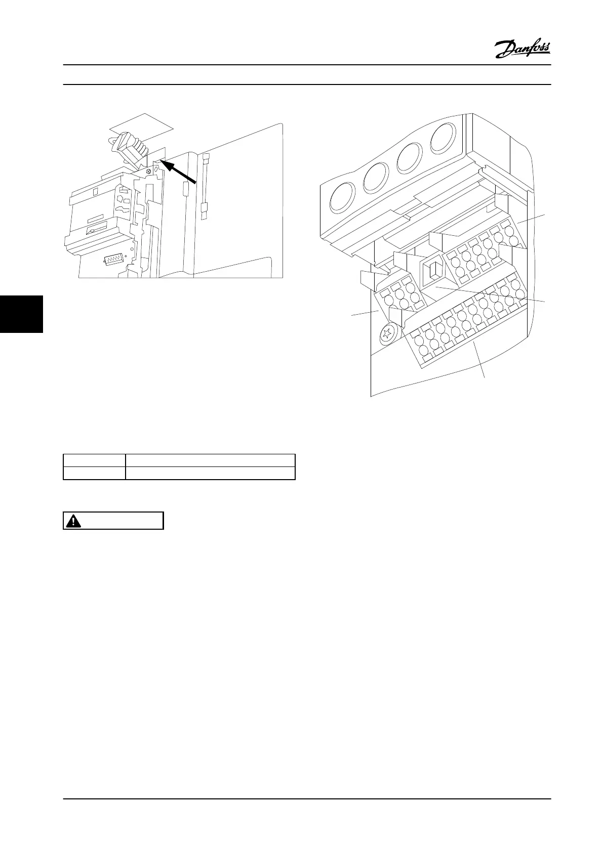
7.5.3 Control Terminals
Drawing Reference Numbers:
1. 10-pole plug digital I/O
2. 3-pole plug RS-485 Bus
3. 6-pole analog I/O
4. USB Connection
61
68
69
39
42
50
53
54
55
12
13
18
19
27
29
32
33
20
37
Figure 7.40 Control Terminals (All Frame Sizes)
7.5.4
Switches S201 (A53), S202 (A54), and
S801
Switches S201 (A53) and S202 (A54) are used to select a
current (0–20 mA) or a voltage (-10 to +10 V) configuration
of the analog input terminals 53 and 54 respectively.
Switch S801 (BUS TER.) can be used to enable termination
on the RS-485 port (terminals 68 and 69). See Figure 7.43.
Default Setting:
S201 (A53)=OFF (voltage input)
S202 (A54)=OFF (voltage input)
S801 (Bus termination)=OFF
Electrical Installation Design Guide
224 Danfoss A/S © Rev. 2014-02-10 All rights reserved. MG34S222
77
 Loading...


