EasyManuals Logo
Home>Danfoss>DC Drives>VLT AutomationDrive FC 300

Danfoss VLT AutomationDrive FC 300 Design Guide

Danfoss VLT AutomationDrive FC 300
296 pages
To Next Page IconTo Next Page
To Previous Page IconTo Previous Page
Page #225 background imageLoading...
Page #225 background image
130BC527.10
Figure 7.35 Control Card Wiring Path for the D3h. Control
Card Wiring for the D1h, D2h, D4h, E1 and E2 Use the Same
Path
130BB187.10
1
Figure 7.36 Control Card Wiring Path for the F1/F3. Control
Card Wiring for the F2/F4 Use the Same Path
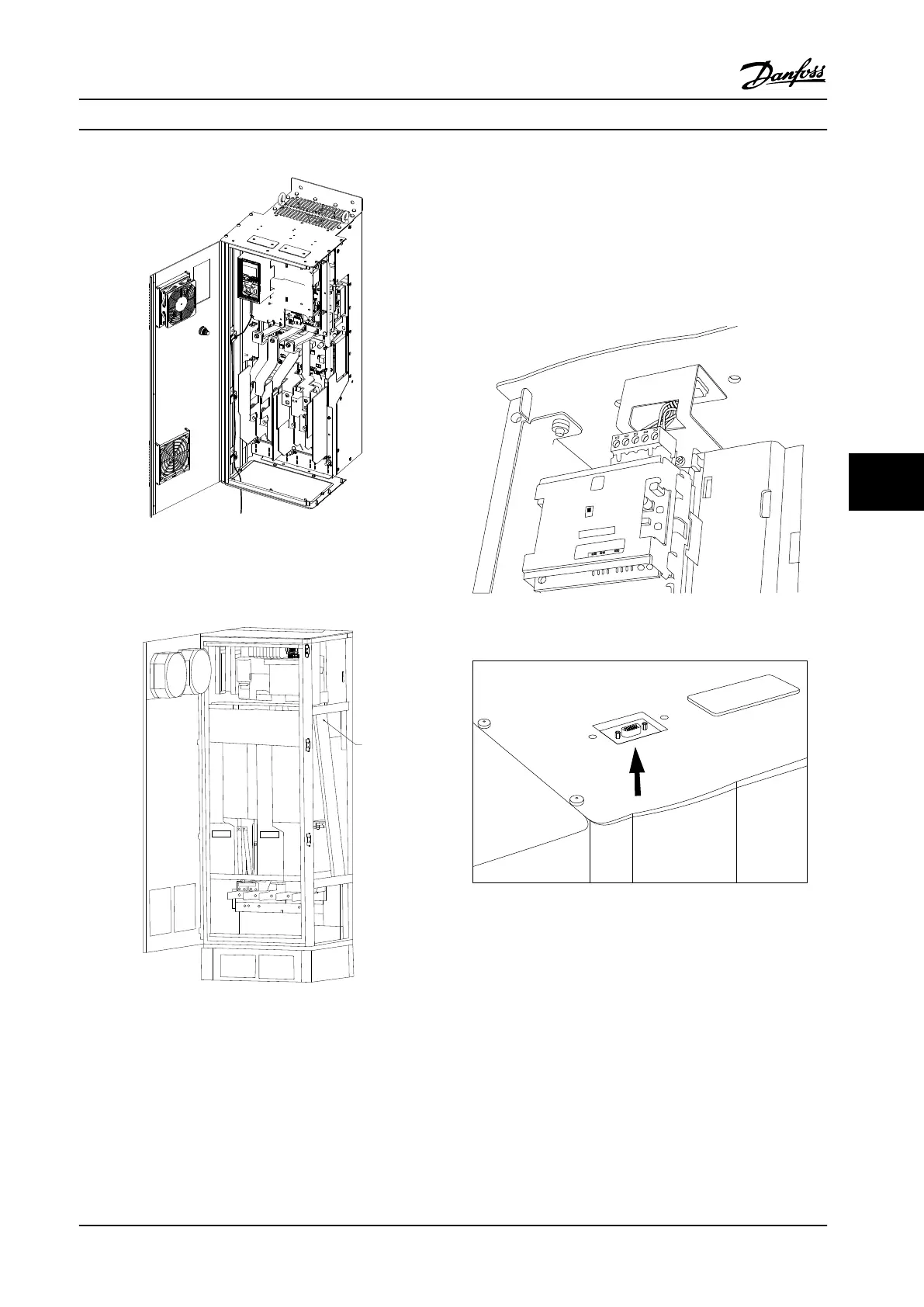
In the D- and E-Frame adjustable frequency drives, it is
possible to connect the serial communication bus from the
top of the unit, as shown in the following figures. On the
IP21/54 (NEMA-1/NEMA-12) unit, a cover plate must be
removed.
The kit number for the serial communication bus top
connection is 176F1742.
130BA867.10
Probus Option A
FC300 Service
Figure 7.37 Top Connection for Serial Communication Bus
130BB255.10
Figure 7.38 Profibus Top Entry Kit, Installed
Electrical Installation Design Guide
MG34S222 Danfoss A/S © Rev. 2014-02-10 All rights reserved. 223
7 7

Table of Contents

Other manuals for Danfoss VLT AutomationDrive FC 300

Questions and Answers:

Question and Answer IconNeed help?

Do you have a question about the Danfoss VLT AutomationDrive FC 300 and is the answer not in the manual?

Danfoss VLT AutomationDrive FC 300 Specifications

General IconGeneral
BrandDanfoss
ModelVLT AutomationDrive FC 300
CategoryDC Drives
LanguageEnglish

Related product manuals