90
80
70
60
50
40
30
20
10
0
(%)
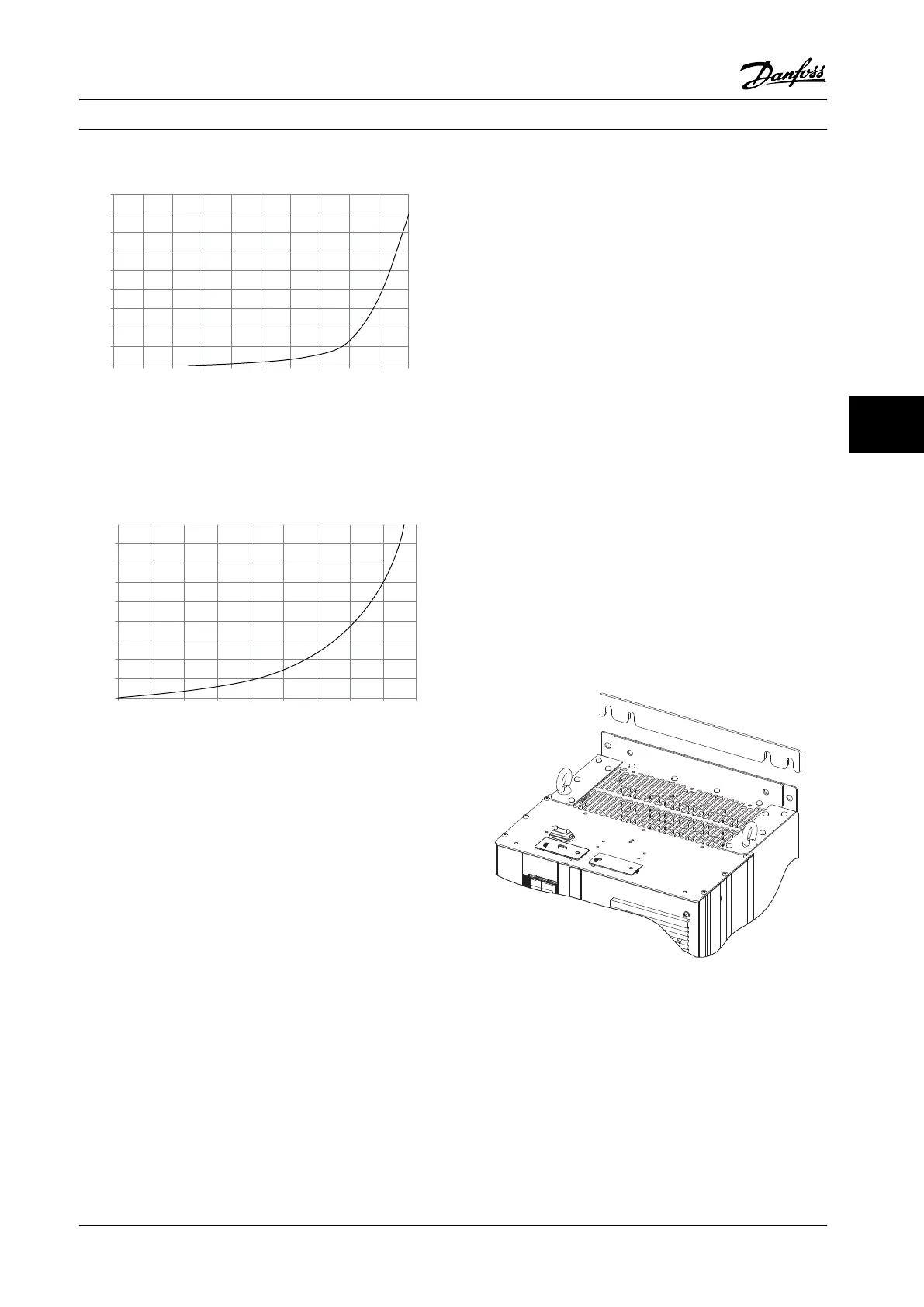
Drive Derating
0 0.2 0.6 2.2 5.8 11.4 18.1 30.8 152.8 210.8
(Pa)
Pressure Change
130BB011.10
69.5
Figure 6.97 E-frame Derating vs. Pressure Change (Large Fan),
P315T5-P400T5 and P500T7-P560T7. Adjustable Frequency
Drive Airflow: 850 cfm (1,445 m
3
/h)
90
80
70
60
50
40
30
20
10
0
(%)
Drive Derating
0 25 50 75 100 125 150 175 225
130BB190.10
200
Pressure Change
Figure 6.98 F1, F2, F3, F4 Frame Derating vs. Pressure Change.
Adjustable Frequency Drive Airflow: 580 cfm (985 m
3
/h)
6.2.10
Wall/Panel Mount Installation
Only the D1h and D2h are recommended to be wall
mounted outside an enclosure due to their IP21 (NEMA 1)
and IP54 (NEMA 12) rating. While the D3h and D4h units
can be wall mounted, it is recommended they be panel
mounted inside an enclosure. The E2 unit is designed only
to be panel mounted within an enclosure.
To install a wall or panel-mounted unit, perform the
following steps:
1. Make sure there is at least 225 mm (8.9 in) of
space between the top of the unit and the
ceiling, and at least 225 mm (8.9) space between
the unit and the floor to provide for adequate
cooling.
2. Make sure there is enough space for cable entry
at the bottom of the unit.
3. Mark the mounting holes according to the instal-
lation drawings and drill holes where indicated.
4. Mount the bolts at the bottom of the unit and lift
the adjustable frequency drive up on the bolts.
5. Tilt the adjustable frequency drive against the
wall and mount the upper bolts.
6. Tighten all four bolts to secure the unit against
the wall.
6.2.11
Pedestal Installation of D-frames
The D7h and D8h adjustable frequency drives are shipped
with a pedestal and a wall spacer. Before securing the
enclosure to the wall, install the pedestal behind the
mounting flange as shown in Figure 6.99.
Figure 6.99 Wall Mounting Spacer
Mechanical Installation Design Guide
MG34S222 Danfoss A/S © Rev. 2014-02-10 All rights reserved. 175
6 6