8.12 Encoder Direction
The direction of the encoder is determined by the order of
the pulses entering the adjustable frequency drive.
Clockwise (CW) direction means channel A is 90 electrical
degrees before channel B.
Counter-clockwise (CCW) direction means channel B is 90
electrical degrees before A.
The direction can be determined by looking into the shaft
end.
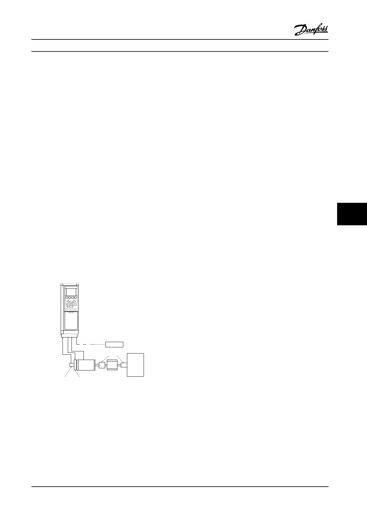
8.13 Closed-loop Drive System
A closed-loop drive system usually consists of the
following:
•
Motor
•
Add
(Gearbox)
(Mechanical Brake)
•
FC 302
•
Encoder as feedback system
•
Brake resistor for dynamic braking
•
Transmission
•
Load
Applications demanding mechanical brake control typically
needs a brake resistor.
Motor
Gearbox
Load
Transmission
Encoder Mech. brake
Brake resistor
130BA120.10
Figure 8.7 Basic Set-up for FC 302 Closed-loop Speed Control
8.14 Stop and Torque Limit
In applications with an external electro-mechanical brake,
such as hoisting applications, it is possible to stop the
adjustable frequency drive via a 'standard' stop command
and simultaneously activate the external electro-
mechanical brake.
The example given below illustrates the programming of
these adjustable frequency drive connections. The external
brake can be connected to relay 1 or 2 (See
chapter 3.9 Mechanical Brake Control). Program terminal 27
to [2] Coast, inverse or [3] Coast and Reset, inverse, and
program terminal 29 to [1] Terminal mode 29 Output and
[27] Torque limit & stop.
If a stop command is active via terminal 18 and the
adjustable frequency drive is not at the torque limit, the
motor ramps down to 0 Hz.
If the adjustable frequency drive is at the torque limit and
a stop command is activated, terminal 29 Output
(programmed to [27] Torque limit and stop) is activated.
The signal to terminal 27 changes from 'logic 1' to 'logic 0',
and the motor starts to coast, thereby ensuring that the
hoist stops even if the adjustable frequency drive itself
cannot handle the required torque, for example due to
excessive overload.
To program the stop and torque limit, connect to the
following terminals:
•
Start/stop via terminal 18
5-10 Terminal 18 Digital Input Start [8]
•
Quickstop via terminal 27
5-12 Terminal 27 Digital Input Coasting Stop,
Inverse [2]
•
Terminal 29 Output
5-02 Terminal 29 Mode Terminal 29 Mode Output
[1]
5-31 Terminal 29 Digital Output Torque Limit &
Stop [27]
•
Relay output [0] (Relay 1)
5-40 Function Relay Mechanical Brake Control [32]
Application Examples Design Guide
MG34S222 Danfoss A/S © Rev. 2014-02-10 All rights reserved. 247
8 8
 Loading...


