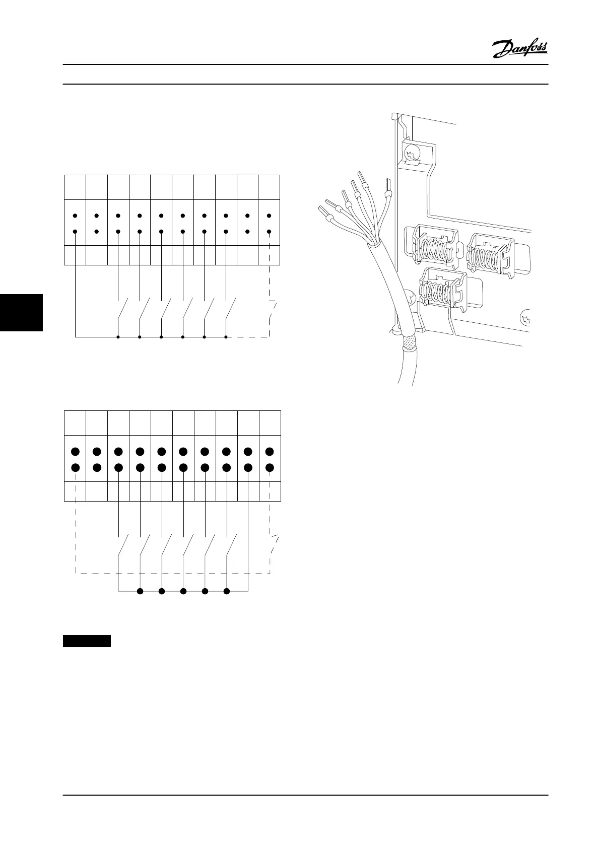
Input Polarity of Control Terminals
12 13 18 19 27 29 32 33 20 37
+24 V DC
0 VDC
130BT106.10
PNP (Source)
Digital input wiring
Figure 7.45 Input Polarity of Control Terminals (PNP Source)
NPN (Sink)
Digital input wiring
12 13 18 19 27 29 32 33 20 37
+24 V DC
0 VDC
130BT107.11
Figure 7.46 Input Polarity of Control Terminals (NPN Sink)
NOTICE!
Use shielded/armored cables to comply with EMC
emission specifications. For more information, see
chapter 7.8 EMC-compatible Installation.
Figure 7.47 Shield Termination and Strain Relief of Control
Cable
Electrical Installation Design Guide
228 Danfoss A/S © Rev. 2014-02-10 All rights reserved. MG34S222
77
 Loading...


