WARNING/ALARM 36, Mains failure
This warning/alarm is only active if the supply voltage to
the frequency converter is lost and 14-10 Mains Failure is
NOT set to OFF. Check the fuses to the frequency
converter.
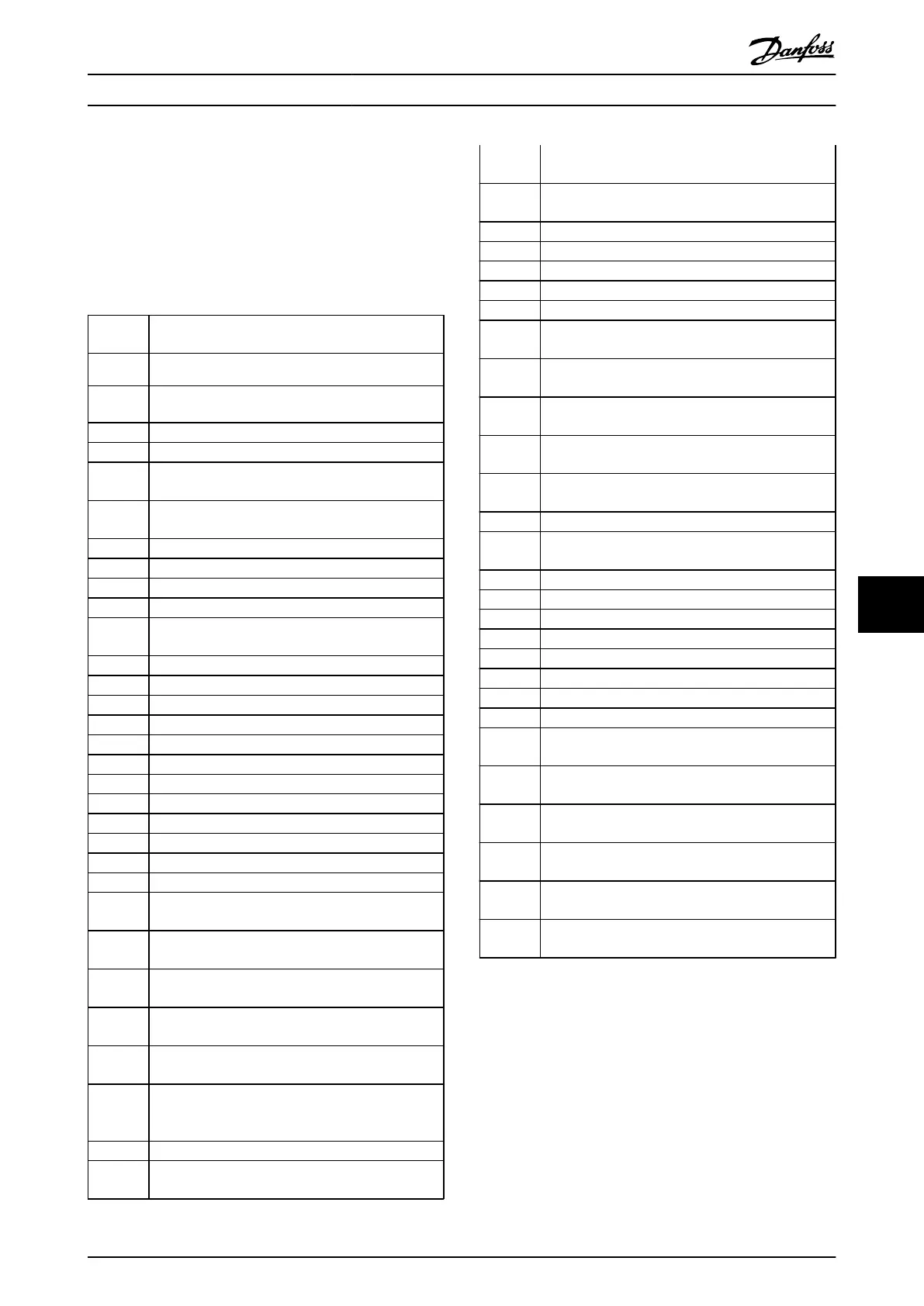
ALARM 38, Internal fault
It may be necessary to contact your Danfoss supplier.
Some typical alarm messages:
0 Serial port cannot be initialized. Serious hardware
failure
256-258 Power EEPROM data is defect or too old
512 Control board EEPROM data is defect or too old
513 Communication time out reading EEPROM data
514 Communication time out reading EEPROM data
515 Application Orientated Control cannot recognize the
EEPROM data
516 Cannot write to the EEPROM because a write
command is on progress
517 Write command is under time out
518 Failure in the EEPROM
519 Missing or invalid Barcode data in EEPROM
783 Parameter value outside of min/max limits
1024-
1279
A cantelegram that has to be sent, couldn't be sent
1281 Digital Signal Processor flash timeout
1282 Power micro software version mismatch
1283 Power EEPROM data version mismatch
1284 Cannot read Digital Signal Processor software version
1299 Option SW in slot A is too old
1300 Option SW in slot B is too old
1301 Option SW in slot C0 is too old
1302 Option SW in slot C1 is too old
1315 Option SW in slot A is not supported (not allowed)
1316 Option SW in slot B is not supported (not allowed)
1317 Option SW in slot C0 is not supported (not allowed)
1318 Option SW in slot C1 is not supported (not allowed)
1379 Option A did not respond when calculating Platform
Version.
1380 Option B did not respond when calculating Platform
Version.
1381 Option C0 did not respond when calculating Platform
Version.
1382 Option C1 did not respond when calculating Platform
Version.
1536 An exception in the Application Orientated Control is
registered. Debug information written in LCP
1792 DSP watchdog is active. Debugging of power part
data Motor Orientated Control data not transferred
correctly
2049 Power data restarted
2064-
2072
H081x: option in slot x has restarted
2080-
2088
H082x: option in slot x has issued a powerup-wait
2096-
2104
H083x: option in slot x has issued a legal powerup-
wait
2304 Could not read any data from power EEPROM
2305 Missing SW version from power unit
2314 Missing power unit data from power unit
2315 Missing SW version from power unit
2316 Missing io_statepage from power unit
2324 Power card configuration is determined to be
incorrect at power up
2325 A power card has stopped communicating while
main power is applied
2326 Power card configuration is determined to be
incorrect after the delay for power cards to register
2327 Too many power card locations have been registered
as present
2330 Power size information between the power cards
does not match
2561 No communication from DSP to ATACD
2562 No communication from ATACD to DSP (state
running)
2816 Stack overflow Control board module
2817 Scheduler slow tasks
2818 Fast tasks
2819 Parameter thread
2820 LCP Stack overflow
2821 Serial port overflow
2822 USB port overflow
2836 cfListMempool to small
3072-
5122
Parameter value is outside its limits
5123 Option in slot A: Hardware incompatible with Control
board hardware
5124 Option in slot B: Hardware incompatible with Control
board hardware
5125 Option in slot C0: Hardware incompatible with
Control board hardware
5126 Option in slot C1: Hardware incompatible with
Control board hardware
5376-
6231
Out of memory
Table 9.4
ALARM 39, Heatsink sensor
No feedback from the heatsink temperature sensor.
The signal from the IGBT thermal sensor is not available on
the power card. The problem could be on the power card,
on the gate drive card, or the ribbon cable between the
power card and gate drive card.
WARNING 40, Overload of Digital Output Terminal 27
Check the load connected to terminal 27 or remove short-
circuit connection. Check 5-00 Digital I/O Mode and
5-01 Terminal 27 Mode.
Troubleshooting VLT Automation Low Harmonic Drive Operating Instructions
MG34O202 - VLT
®
is a registered Danfoss trademark 155
9 9
 Loading...


