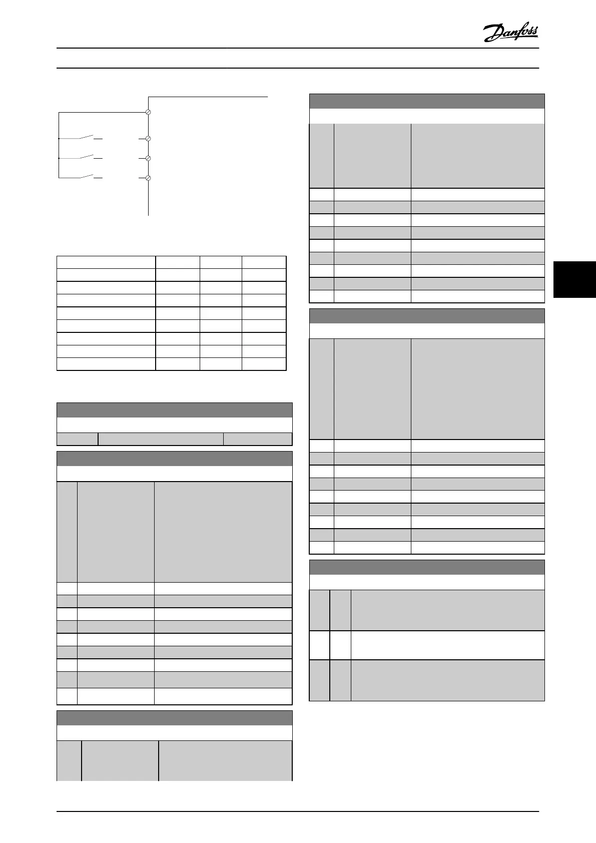
[P 5-13=Preset ref. bit 0]
Preset
[P 5-14=Preset ref. bit 1]
[P 5-15=Preset ref. bit 2]
10101010
76543210
29
12
(+24V)
11001100
32
11110000
33
130BA149.10
Illustration 6.10
Preset ref. bit 2 1 0
Preset ref. 0 0 0 0
Preset ref. 1 0 0 1
Preset ref. 2 0 1 0
Preset ref. 3 0 1 1
Preset ref. 4 1 0 0
Preset ref. 5 1 0 1
Preset ref. 6 1 1 0
Preset ref. 7 1 1 1
Table 6.4
3-11 Jog Speed [Hz]
Range: Function:
0 Hz* [0.0 - par. 4-14 Hz]
3-15 Reference Resource 1
Option: Function:
Select the reference input to be used
for the first reference signal.
3-15 Reference Resource 1,
3-16 Reference Resource 2 and
3-17 Reference Resource 3 define up to
three different reference signals. The
sum of these reference signals
defines the actual reference.
[0] No function
[1] * Analog input 53
[2] Analog input 54
[7] Frequency input 29
[8] Frequency input 33
[11] Local bus reference
[20] Digital pot.meter
[21] Analog input X30-11 (General Purpose I/O Option Module)
[22] Analog input X30-12 (General Purpose I/O Option Module)
3-16 Reference Resource 2
Option: Function:
Select the reference input to be
used for the second reference
signal. 3-15 Reference Resource 1,
3-16 Reference Resource 2
Option: Function:
3-16 Reference Resource 2 and
3-17 Reference Resource 3 define up
to three different reference signals.
The sum of these reference signals
defines the actual reference.
[0] No function
[1] Analog input 53
[2] Analog input 54
[7] Frequency input 29
[8] Frequency input 33
[11] Local bus reference
[20] * Digital pot.meter
[21] Analog input X30-11
[22] Analog input X30-12
3-17 Reference Resource 3
Option: Function:
Select the reference input to be
used for the third reference signal.
3-15 Reference Resource 1,
3-16 Reference Resource 2 and
3-17 Reference Resource 3 define up
to three different reference signals.
The sum of these reference signals
defines the actual reference.
[0] No function
[1] Analog input 53
[2] Analog input 54
[7] Frequency input 29
[8] Frequency input 33
[11] * Local bus reference
[20] Digital pot.meter
[21] Analog input X30-11
[22] Analog input X30-12
5-00 Digital I/O Mode
Option: Function:
Digital inputs and programmed digital outputs are
pre-programmable for operation either in PNP or NPN
systems.
[0] * PNP
Action on positive directional pulses (↕). PNP systems
are pulled down to GND.
[1] NPN
Action on negative directional pulses (↕). NPN
systems are pulled up to +24 V, internally in the
frequency converter.
NOTE
Once this parameter has been changed, it must be
activated by performing a power cycle.
How to Programme the Low Ha... VLT Automation Low Harmonic Drive Operating Instructions
MG34O202 - VLT
®
is a registered Danfoss trademark 77
6
6
 Loading...


